Gesamtbetrag:
zzgl. Mwst.
Hardware and BSP Reference Manual - phyGATE-Tauri-L (i.MX 8M Mini) Kit (L-1028e.A4)
Table of Contents
Notes about this Manual
Usage
The information in this manual is valid for all standard variants of the phyGATE Tauri-L industrial gateway from PHYTEC Messtechnik GmbH. An overview of all devices and variants to which the descriptions apply can be found in Product Information.
Before using the document, please check whether it also corresponds to the latest version. The latest version of the manual and other technical documents can be found on the product page for the device at www.phytec.de.
Warning
For proper installation and safe operation of the device, the operating instructions and in particular the safety instructions contained therein must be carefully read and observed.
Symbols
The manual uses various symbols to indicate helpful and safety-critical notes. Below you will find an explanation of each symbol's meaning.
Warning
This symbol indicates safety-critical information. The warnings must be observed!
Tip
This symbol indicates general notes and helpful information in handling the device.
Safety Instructions and Liability
Intended Use
The phyGATE Tauri-L gateway is designed for monitoring, processing, and communicating machine and sensor data in industrial environments. For data communication, the devices provide various typical industrial interfaces for connection to surrounding devices.
This PHYTEC standard gateway is supplied exclusively as an OEM device by PHYTEC Messtechnik GmbH and requires an adaptation of the operating software for the intended application by the distributor of the device.
Warning
The device must not be used in a manner not specified in this manual to avoid damage to the protection provided by the equipment.
L’appareil ne doit pas être utilisé d'une façon non spécifiée dans ce manuel afin éviter d’endommager la protection fournie par l'équipement.
General Safety Instructions
For commissioning, development work, and assembly, the operating instructions for the device must be used. Knowledge in the following areas is required:
- Electronic circuitry
- Working in electrostatically protected areas
- Accident prevention regulations
- On-site valid rules and regulations for occupational safety
These devices may only be commissioned and installed by adequately qualified personnel with basic electrical knowledge! The device must be handled with care in every phase of its life cycle, in order to prevent destruction by electrostatic discharge or mechanical stress, for example.
To ensure functional safety, the device must be powered by a SELV/PELV power supply. The gateway must be mounted on a top-hat rail in a fire save control cabinet for permanent use.
Improper modifications and repairs may impair the integrated protective functions and the electromagnetic behavior of the device. This can cause malfunction of the device, interference with connected and surrounding devices, or personal injury. Therefore, work on this device may only be carried out by the manufacturer.
Warning
To ensure functional safety, the device must be powered by a SELV/PELV power supply. The gateway must be mounted on a top-hat rail in a fire save control cabinet for permanent use.
Pour garantir la sécurité fonctionnelle, l’appareil doit être alimenté par une alimentation SELV/PELV. Pour une utilisation permanente, la passerelle doit être montée sur un rail profilé chapeau dans une armoire de commande coupe-feu.
Disposal
The operator of these devices must ensure that there is no danger to persons or property in the event of a defect or malfunction of the device. In case of non-repairable defects and device malfunctions, the devices must be taken out of operation and disposed of properly.
Warning
The device must not be disposed of in household waste!

Liability
Improper use and connection of these devices, as well as subsequent processing of these devices (e.g. soldering work on the printed circuit board), lead to exclusion of liability on the part of the manufacturer. Please observe the corresponding information in the operating instructions for proper installation.
Product Information
Product Names and Variants
The phyGATE Tauri-L gateway is available in different variants and expansion stages, which differ in the scope of performance and functions. The following table gives an overview of available variants of the gateway and an explanation for the identification of the article number.
Note
The article numbers have an index ".Ax" where x determines the product revision.
| Parent Product | Article Number | Technical Features |
|---|---|---|
|
|
|
|
| |
|
|
phyGATE Tauri-L Variants
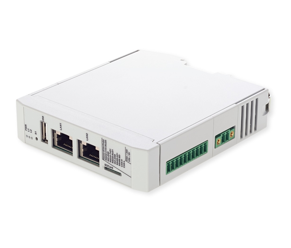
Product Overview
The phyGATE Tauri-L has several interfaces and controls/displays which are shown in the following figures.
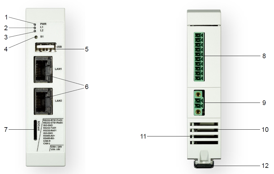
phyGATE Tauri-L Interfaces
PB-03420-003.Ax | PB-03420-001.Ax | PB-03420-002.Ax | Controls/Displays |
| X | X | X | 1. Power-LED green |
| X | X | X | 2. User-LED red (freely configurable) |
| X | X | X | 3. User-LED yellow (freely configurable) |
| X | X | X | 4. Button (freely configurable) |
| X | X | X | 5. USB interface (Typ A) |
| X | X | X | 6. Ethernet interface (RJ45) |
| X | X | X | 7. Micro-SD Slot |
| X | X | 8. RS232, RS485, CAN interface (configurable) | |
| X | X | X | 9. Supply connection |
| X | X | X | 10. Boot-Switch (Concealed, on opposite housing side) |
| X | X | X | 11. Air vents |
| X | X | X | 12. Extension interface under a top-hat rail and top-hat rail clip (35mm) |
| X | (13.) SMA antenna connector | ||
| X | (14.) internal miniPCIe slot (USB only) | ||
| X | (15.) SIM card socket |
phyGATE Tauri-L Interface List
Nameplate
The nameplate of the phyGATE Tauri-L gateway is located on the side of the housing. Here you will find essential information about your device.
Technical Data
Electrical Data | |
| min. 12 VDC (-10 %) |
Power consumption | PB-03420-001: max. 300 mA @ 24 VDC |
| PB-03420-002: max. 400 mA @ 24 VDC | |
| PB-03420-003: max. 300 mA @ 24 VDC | |
| Power adapter type | SELV/PELV |
| Hardware Specification | |
CPU type | NXP i.MX 8M mini Quad-Core Cortex-A53 + Cortex-M4 |
RAM | 2 GB |
eMMC | 8 GB |
Ethernet | 2x 10/100/1000 Mbit/s |
USB | USB 2.0 |
CAN (optional) | 1 Mbit/s, CAN FD, isolated |
|
|
| Mass storage | microSD card slot |
| Additional features | TPM chip, Temperature sensor |
RTC | GoldCap for real-time functionality |
| 1x user button |
| Software Specification | |
| Operating system | Linux (Yocto) |
Security Features | Device-Management / Cloud-Update concept |
Mechanical Data | |
| Housing type | Phoenix ICS |
Housing material | Polyamide |
| Mounting type | Top-hat rail mounting according to DIN EN 60715 |
IP protection class | max. IP20 |
| 100 mm / 25 mm / 110 mm |
| PB-03420-001.Ax | |
| PB-03420-002.Ax | |
| 100 mm / 50 mm / 110 mm | |
| PB-03420-003.Ax | |
| with customer adapter PCB | |
Weight (depending on variant) | max. 250 g (depending on variant) |
Environmental Data | |
Storage temperature | -20 °C - +70 °C |
| Operating temperature | -20 °C - +60 °C |
Humidity | 10% - 95% non condensing |
| IP protection class control cabinet | min. IP44 |
Technical Data Information
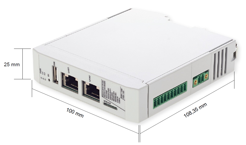
phyGATE-Tauri-L Measurements
Package Contents/Accessories
phyGATE Tauri-L Stand-Alone Device | phyGATE Tauri-L Kit Upgrade |
|---|---|
You'll find the following content within your stand-alone phyGATE Tauri-L packaging:
 | The phyGATE Tauri-L Kit upgrade for the easy start of development:
|


phyGATE-Tauri-L Kit Contents
Certification
The phyGATE Tauri-L has been approved for sale and use on the European market and meets the criteria for CE marking according to:
- DIN EN 61000-6-2:2019-11 EMV Interference immunity for industrial areas
- DIN EN 61000-6-3:2020-09 EMV Interference emissions for living area
The CE declaration of conformity for the device can be found online on the product page at www.phytec.de.
Warning
Modification of the device, such as adjustments to the software or the use of additional devices in conjunction with the phyGATE Tauri-L Gateway, can influence the electrical properties of the device. In this case, the validity of the CE declaration of conformity is void. For a valid CE marking, a renewed approval by the operator must be carried out in this case.
Technical Documentation and Support
Technical documentation for the product can be found on our product page online at www.phytec.de. If you have any questions or suggestions regarding the product, we look forward to hearing from you.
Technical Product Information
Block Diagram

phyGATE-Tauri-L Block Diagram
Electrical Connection
The phyGATE Tauri-L gateway has various interfaces for connection to the surrounding infrastructure. The following table lists the connections with the matching mating connectors.
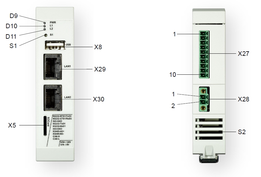
phyGATE-Tauri-L Infrastructure Interfaces
phyGATE Tauri-L Interfaces | |||
Reference | Connection | Device Socket | Mating Connector |
X28 | DC supply | Phoenix MC 1,5/ 2-GF-3,81 | Phoenix MC 1,5/ 2-STF-3,81 |
X29 | Ethernet 1 | RJ45 | RJ45 |
X30 | Ethernet 0 | RJ45 | RJ45 |
X8 | USB | USB-A | USB-A |
X5 | SD Karte | microSD-Slot | MicroSD-Karte |
X27 | RS232 / RS485 / CAN | Phoenix MC 1,5/10G-3,5 | Phoenix MC1,5/10-ST-3,5 |
S1 | User Input Button | --- | --- |
S2 | Boot-Switch | --- | --- |
| D9 | Power-LED (green) | --- | --- |
| D10 / D11 | User-LEDs (red / yellow) | --- | --- |
| (X23) | Antenna connector | SMA (female) | SMA (male) |
phyGATE Tauri-L Interfaces and Mating Connectors
Pinout of Non-standard Interfaces | |||
| Reference | Connection | Pin | Function |
|
| 1 | +24 VDC |
| 2 | Device GND | ||
|
| 1 | RS232_0_TX |
| 2 | RS232_0_RX | ||
| 3 | GND_ISO | ||
| 4 | RS232_1_TX | ||
5 | RS232_1_RX | ||
6 | GND_ISO | ||
| 7 | RS485_A | ||
| 8 | RS485_B | ||
| 9 | CANH | ||
| 10 | CANL | ||
phyGATE Tauri-L Interface Pinouts
Tip
For the phyGATE Tauri-L variants with RS232 / RS485 / CAN, the function of the pins can be configured by the application software.
Warning
For permanently connected equipment: supply wiring requirements, requirements for any external switch or circuit-breaker, and external over-current protection devices, we recommend that the switch or circuit-breaker be near the equipment.
Warning
All signals at connector X27 are galvanically decoupled from the GND reference potential of the board and the supply voltage of the phyGATE Tauri-L.
Mechanical Connection
The phyGATE Tauri-L gateway housing is designed to be mounted on a top-hat rail in the control cabinet. For mounting on the top-hat rail, there is a mounting device on the housing which allows a tool-free and safe mounting on a 35 mm top-hat rail.
Warning
The installation environment, such as the control cabinet in which the device is installed, must meet, as a minimum, the IP44 specifications and must be fireproof.
L'environnement de l’installation du dispositif, comme l'armoire de commande dans laquelle l’appareil est installé, doit répondre, au minimum, aux spécifications IP44 et être ignifuge.
Warning
For intended use, the device must be installed on a 35 mm top-hat rail according to DIN EN 60715.
Pour l'utilisation à laquelle il est destiné, l’appareil doit être monté sur un rail profilé chapeau de 35 mm conformément à la norme DIN EN 60715.
Warning
To prevent malfunction or destruction of the device due to overheating, it is essential to ensure that the ventilation slots are not covered by surrounding components, cables, and other objects. The air must be able to circulate freely around the housing to dissipate heat.
Pour éviter tout dysfonctionnement ou destruction de l’appareil en cas de surchauffe, il est indispensable de s’assurer que les fentes d'aération ne sont pas couvertes par des composants environnants, des câbles et autres objets. L'air doit pouvoir circuler librement autour du boîtier pour dissiper la chaleur.
Getting Started with the phyGATE Tauri-L Gateway
Introduction
To easily get started with your phyGATE Tauri-L device, you'll find a description with the necessary tools and provision of the know-how to work with the Linux Board Support Package (BSP) for the phyCORE-i.MX 8M Mini below. It shows you step by step, how to set up the device for an easy start in development, including:
- essential connection of the device and getting access to the OS
- installing and using the appropriate tools and sources
- building custom kernels
- deploying the OS in order to operate the software and hardware
Tip
All necessary information, software, and other downloads for quick commissioning can be found on the phyGATE Tauri-L product page online at www.phytec.de.
Requirements
You'll need the following components to get started quickly with this installation guide:
- phyGATE Tauri-L device
- 1x MicroSD Card with prepared prebuilt image
- 1x 24 VDC SELV/PELV Mains-Adapter with a mating connector to device supply connector
- 1x LAN cable
|
|
|
|
phyGATE-Tauri-L Component Requirements
Tip
The phyGATE Tauri-L kit upgrade contains all the necessary components to easily start installing the device.
Prepare the SD Card for Device Boot
To prepare the microSD card for the device boot, please follow the steps mentioned below.
Tip
If you have a prepared SD card from the phyGATE Tauri-L Kit, this section can be skipped.
If you are using your own SD Card, you'll have to download the prebuilt image file and burn it to the SD card first:
- Download the Image file located at https://download.phytec.de/Software/Linux/BSP-Yocto-i.MX8MM/BSP-Yocto-NXP-i.MX8MM-PD22.1.0/images/ampliphy-vendor/phygate-tauri-l-imx8mm-2/phytec-headless-image-phygate-tauri-l-imx8mm-2.sdcard
- Burn the Image to the SD Card (see the descriptions below).
If you are using Windows:
To burn the Image to the SD Card, you'll have to use an image burner tool of your choice. The description below is based on the WIN32 Disk Imager Tool.
Please follow the steps below to get your SD card ready with WIN32 Disk Imager:
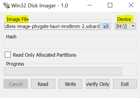
WIN32 Disk Imager Interface
- Choose the Image File and your microSD device
- Press 'Write' to burn the Image on your microSD card
Warning
Be sure the right Device is selected to avoid damage to other storage devices connected to your computer.
If you are using Linux:
- Open Terminal on Host-System and type the following command to burn the Image:
Host$ sudo dd if=<IMAGENAME>-<MACHINE>.sdcard of=/dev/<your_device> bs=1M conv=fsync status=progress
Booting the Board
Insert the microSD card
To use the SD card as a boot device, you'll have to put the prepared SD card into the microSD card slot located in the front of the device's housing.
Set Boot Switch
The phyGATE Tauri-L provides a boot switch to choose the boot source of the device. You can choose either eMMC (DIP at position '1') or SD Card (DIP at position 'ON') as a boot source.
The red switch is located at the opposite side of the housing referenced to the supply connector X28. You can reach the switch between the vent slots of the housing with help of a small item e.g. a screwdriver to switch the position of the DIP switch.
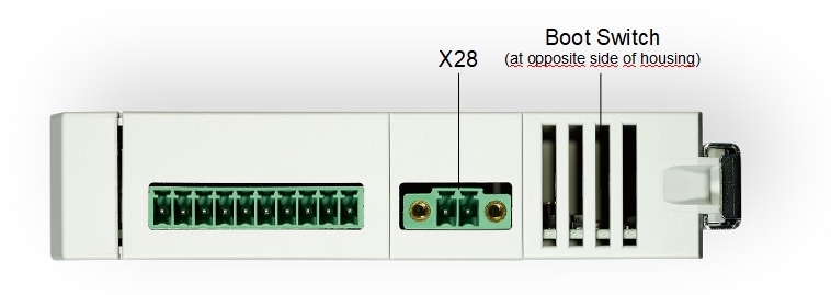
phyGATE Tauri-L Boot Switch Location
Powering the Board
The phyGATE Tauri-L has a 2 pin Phoenix Contact MINI COMBICON power connector (counterpart Phoenix Contact MC 1,5/ 2-STF-3,5 or MC 1,5/ 2-ST-3,5). The permissible input voltage is 12 VDC to 36 VDC. A 24 VDC adapter with a minimum current rating of 1A is recommended to supply the board. The power adapter must be of SELV/PELV classification.
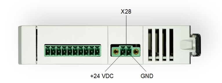
phyGATE Tauri-L Power Connector
After turning the power supply on, the green LED D9 in the device front will light up and the boards will start booting.
Warning
Please note the polarity of the power connector X28. Make sure that your power adapter is correctly set up to use the polarity as shown in the picture above!
Do not make any electrical changes to the interfaces and cables while the board is connected to power. This is to avoid damage to the device!
Tip
Be aware that as soon as the phyGATE Tauri-L is supplied with power, the SD Card boot sequence will begin. Ensure that all cables are connected on the board!
Tip
With help of the red user LED in the front of the device housing, you can see if the boot process is running. The LED is flickering during the boot process.
Connecting the OS via SSH
Once the board is done booting, you can connect to the board via Ethernet and SSH. Therefore, you need to connect an RJ45 Ethernet cable between the phyGATE Tauri-L and your computer. Make sure that the IP configuration of your computer is configured as follows:
- IP address: 192.168.3.10
- Netmask: 255.255.255.0
Now you are able to log in via SSH. Therefore, please use the following login data:
- IP Adress: 192.168.3.11
- Port: 22
- User: root
- Password: no password
Warning
For the purpose of development, the Tauri-L is delivered with root access without password. Please change this in our final product. Otherwise, there will be a security risk.
If you are using Windows:
For the SSH connection under Windows, you can use an SSH client of your choice. The description below is based on PuTTY:
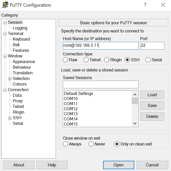
SSH Connection (PuTTY Interface)
- Configure Host Name as "root@192.168.3.11"
- Press 'Open' to connect the device via SSH
If you are using Linux:
host$ ifconfig <eth-interface> 192.168.3.10 up
host$ ssh root@192.168.3.11
Yogurt Vendor (Phytec Vendor Distribution) 2.6.2 phygate-tauri-l-imx8mm-2 ttymxc2 phygate-tauri-l-imx8mm-2 login:
Building the BSP
This section will guide you through the general build process of the i.MX 8M Mini BSP using the phyLinux script. For more information about our meta-layer or Yocto in general visit: L-813e.A12 Yocto Reference Manual.
Basic Set-Up
- If you have never created a PHYTEC BSP with Yocto on your computer, you should take a closer look at the chapter BSP Workspace Installation in the L-813e.A12 Yocto Reference Manual.
Finding the Right Software Platform
The i.MX 8M Mini BSP is a unified BSP, which means, it supports a set of different PHYTEC carrier boards (CB) with different Systems on Module (SOMs). For the Tauri-L there is one machine included:
#@TYPE: Machine
#@NAME: phygate-tauri-l-imx8mm-2 #@DESCRIPTION: PHYTEC phyGATE-Tauri i.MX8M Mini 2GB RAM
#@ARTICLENUMBERS: PB-03420
#@SUPPORTEDIMAGE: phytec-headless-image/ampliphy-vendor
Get the BSP
There are two ways to get the BSP sources. You can download the complete BSP sources from our download page: BSP-Yocto-i.MX8MM; or you can build it yourself with Yocto. This is particularly useful if you want to make customizations.
The phyLinux script is a basic management tool for PHYTEC Yocto BSP releases written in Python. It is mainly a helper to get started with the BSP structure.
- Create a fresh project folder, get phyLinux, and make the script executable:
host$ mkdir ~/yocto
host$ cd ~/yocto
host$ wget https://download.phytec.de/Software/Linux/Yocto/Tools/phyLinux
host$ chmod +x phyLinux
host$ ./phyLinux init
- During the execution of the init command, you need to choose your processor platform (SoC), PHYTEC's BSP release number, and the hardware you are working on.
Options | Tauri-L |
|---|---|
| SoC Platforms | imx8mm |
| Release | PD-BSP-Yocto-NXP-i.MX8MM-PD22.1.0 |
| Machine | phygate-tauri-l-imx8mm-2 |
If you cannot identify your board with the information given in the selector, have a look at the invoice for the product. And have look at https://www.phytec.de/bsp-download/?bsp=BSP-Yocto-NXP-i.MX8MM-PD22.1.0
- It is also possible to pass this information directly using command line parameters:
host$ MACHINE=phygate-tauri-l-imx8mm-2 ./phyLinux init -p PD-BSP-Yocto-NXP-i.MX8MM-PD22.1.0
Build Process
After you have downloaded all the metadata with phyLinux init, you have to set up the shell environment variables. This needs to be done every time you open a new shell for starting builds. We use the shell script provided by Poky in its default configuration.
- From the root of your project directory, type:
host$ source sources/poky/oe-init-build-env
Note
This needs to be done every time you open a new shell for starting builds.
- The current working directory of the shell should change to build/.
- Open the main configuration file and you need to accept the GPU and VPU binary license agreements. You have to uncomment the corresponding line.
host$ vim conf/local.conf
# Uncomment to accept NXP EULA
# EULA can be found under ../sources/meta-freescale/EULA
ACCEPT_FSL_EULA = "1"
- Build your image:
host:~/yocto/build$ bitbake phytec-headless-image
BSP Images
All images generated by Bitbake are deployed to ~/yocto/build/tmp/deploy/images/phygate-tauri-l-imx8mm-1/.
The following list shows for example all files generated for the i.MX 8M Mini phygate-tauri-l-imx8mm-1 machine:
- U-Boot: u-boot.bin
- U-Boot-SPL: u-boot-spl.bin
- lpddr4 binary files: lpddr4_pmu_train_1d_dmem.bin, lpddr4_pmu_train_1d_imem.bin, lpddr4_pmu_train_2d_dmem.bin, lpddr4_pmu_train_2d_imem.bin
- Kernel: Image
- Kernel device tree file: oftree
- imx8mm-phy*.dtbo: Kernel device tree overlay files
- Root filesystem: phytec-headless-image-phygate-tauri-l-imx8mm-2.tar.gz, phytec-headless-image-phygate-tauri-l-imx8mm-1.manifest
- SD card image: phytec-headless-image-phygate-tauri-l-imx8mm-2.sdcard
Updating Software
In this section, we explain how to Linux on target/host to update the images in eMMC.
Tip
Updating the eMMC from the bootloader is also possible but requires a serial console available. You need to open the housing to connect a cable.
Therefore it might be easier to boot into linux using a SD card use ssh to flash the image. This is decsribed in this manual. For more information on using the bootloader, refer to the corresponding i.MX8M Mini manual.
Updating eMMC via Network
i.MX 8M Mini boards have an Ethernet connector and can be updated over a network. Be sure to set up the development host correctly. The IP needs to be set to 192.168.3.10, the netmask to 255.255.255.0, and a TFTP server needs to be available.
From a high-level point of view, an eMMC device is like an SD card. Therefore, it is possible to flash the image <name>.sdcard (or <name>.sdcard.bz2) from the Yocto build system directly to the eMMC. The image contains the bootloader, kernel, device trees, and root filesystem.
Updating eMMC in Linux on Target
You can update the eMMC from your target.
Tip
A working network is necessary!
- Take an uncompressed or compressed image on the host and send it with ssh through the network (then uncompress it, if necessary) to the eMMC of the target with a one-line command:
target$ ssh <USER>@192.168.3.10 "dd if=<path_to_file>/phytec-headless-image-phygate-tauri-l-imx8mm-2.sdcard" | dd of=/dev/mmcblk2
Updating eMMC in Linux on Host
It is also possible to update the eMMC from your Linux host. As before, you need a complete image on your host.
Tip
A working network is necessary!
- Show your available image files on the host:
host$ ls
phytec-headless-image-phygate-tauri-l-imx8mm-2.sdcard
- Uncompress and send the image with the dd command combined with ssh through the network to the eMMC of your device:
host$ dd if=phytec-headless-image-phygate-tauri-l-imx8mm-2.sdcard status=progress | ssh root@192.168.3.11 "dd of=/dev/mmcblk2"
Updating eMMC via SD Card
Even if there is no network available, you can update the eMMC. For that, you only need a ready-to-use image file (*.sdcard) located on the SD card. Because the image file is quite large, you have to enlarge your SD card to use its full space (if it was not enlarged before). To enlarge your SD card, see Resizing ext4 Root Filesystem.
Updating eMMC via SD Card in Linux on Target
You can also update the eMMC under Linux. You only need a complete image saved on the SD card (e.q. phytec-headless-image-phygate-tauri-l-imx8mm-2.sdcard).
- Show your saved image files on the SD card:
target$ ls
phytec-headless-image-phygate-tauri-l-imx8mm-2.sdcard
- Show list of available MMC devices:
target$ ls /dev | grep mmc
mmcblk1
mmcblk1p1
mmcblk1p2
mmcblk2
mmcblk2boot0
mmcblk2boot1
mmcblk2p1
mmcblk2p2
mmcblk2rpmb
- Write the image to the eMMC of phyGATE-Tauri (MMC device 2 WITHOUT partition):
target$ dd if=phytec-headless-image-phygate-tauri-l-imx8mm-2.sdcard of=/dev/mmcblk2
- After a complete write, your board can boot from eMMC.
RAUC
The RAUC (Robust Auto-Update Controller) mechanism support has been added to meta-ampliphy. It controls the procedure of updating a device with new firmware. This includes updating the Linux kernel, Device Tree, and root filesystem. PHYTEC has written an online manual on how we have intergraded RAUC into our BSPs: L-1006e.A3 RAUC Update & Device Management Manual
Device Tree (DT)
Introduction
The following text briefly describes the Device Tree and can be found in the Linux kernel (linux/Documentation/devicetree/usage-model.txt).
"The "Open Firmware Device Tree", or simply Device Tree (DT), is a data structure and language for describing hardware. More specifically, it is a description of hardware that is readable by an operating system so that the operating system doesn't need to hardcode details of the machine.
The kernel documentation is a really good source for a DT introduction. An overview of the device tree data format can be found on the device tree usage page at devicetree.org.
PHYTEC i.MX 8M Mini BSP Device Tree Concept
The following sections explain some rules we have defined on how to set up device trees for our i.MX 8M Mini SoC-based boards.
Device Tree Structure
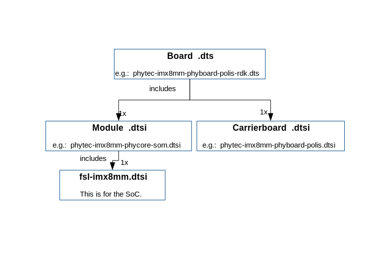
Device Tree Structure
- Module .dtsi - Module includes all devices mounted on the SoM, such as PMIC and RAM.
- Carrierboard.dtsi - Devices that come from the i.MX 8M Mini SoC but are just routed down to the carrier board and used there are included in this dtsi.
- Board.dts - include the carrier board and module dtsi files. There may also be some hardware configuration nodes enabled on the carrier board or the module (i.e. the Board .dts shows the special characteristics of the board configuration). For example, there are phyCORE-i.MX 8M Mini SOMs which may or may not have a MIPI DSI to LVDS converter mounted. The converter is enabled (if available) in the Board .dts and not in the Module .dtsi
From the root directory of the Linux Kernel our devicetree files for i.MX8M platforms can be found in arch/arm64/boot/dts/freescale/ .
Device Tree Overlay
Device Tree overlays are device tree fragments that can be merged into a device tree during boot time. These are for example hardware descriptions of an expansion board. They are instead of being added to the device tree as an extra include, now applied as an overlay. They also may only contain setting the status of a node depending on if it is mounted or not. The device tree overlays are placed next to the other device tree files in our Linux kernel repository in the subfolder arch/arm64/boot/dts/freescale/overlays.
Available overlays for phygate-tauri-l-imx8mm-2:
imx8mm-phygate-tauri-analog_IO.dtso
imx8mm-phygate-tauri-rs232-rs232.dtso
imx8mm-phygate-tauri-rs232-rs485.dtso
imx8mm-phygate-tauri-rs232-rs485-switchable.dtso
imx8mm-phygate-tauri-rs232-rts-cts.dtso
If an overlay should be applied or not can be set during runtime and will have an effect after a reboot. The overlays are applied in the bootloader after the boot command is called and before the kernel is loaded. The following sections explain how it is done.
Set ${overlays} variable
The ${overlays} U-Boot environment variable contains a space-separated list of overlays that will be applied during boot. Depending on the boot source the overlays have to either be placed in the boot partition of eMMC/SD-Card or are loaded over tftp. Overlays set in the $KERNEL_DEVICETREE Yocto machine variable will be automatically added to the boot partition of the final sdcard image.
The ${overlays} variable can be either set directly in the U-Boot environment. Or be a part of the external bootenv.txt environment. The ${overlays} variable loaded from the external environment will always overwrite the value from the environment saved directly in the flash. On default, the ${overlays} variable is not set directly in the U-Boot environment but comes from the external bootenv.txt environment file. It is also located in the boot partition of the sdcard image. You can read and write the file on the booted target:
target$ cat /boot/bootenv.txt
overlays=imx8mm-phyboard-polis-peb-eval-01.dtbo imx8mm-phyboard-polis-peb-av-010.dtbo
Changes will then take effect after the next reboot.
If no bootenv.txt file is available the overlays variable can be set directly in the U-Boot environment.
u-boot=> setenv overlays imx8mm-phyboard-polis-peb-av-010.dtbo
u-boot=> printenv overlays
overlays=imx8mm-phyboard-polis-peb-av-010.dtbo
u-boot=> saveenv
If you want to change the overlay variable in a non-persistent way, for example for testing:
u-boot=> setenv no_bootenv 1
u-boot=> setenv overlays <overlays you like to test>
u-boot=> boot
Note
When the board is booted for the first time or when you reset the environment to the default (u-boot=> env default -a), the environment is automatically saved in flash, so the board must boot at least once until you can customize the environment in a non-persistent way.
More information about the external environment can be found in U-Boot External Environment.
We use the ${overlays} variable for overlays describing expansion boards and cameras that can not be detected during run time.
To prevent applying overlays listed in the ${overlays} variable during boot the ${no_overlays} variable can be set to 1 in the bootloader environment.
u-boot=> setenv no_overlays 1
u-boot=> saveenv
Extension Command
The u-boot extension command makes it possible to easily apply overlays that have been detected and added to a list by the board code callback extension_board_scan().
In the BSP the overlays applied in this way are used to disable components that are not populated on the SoM. The detection is done with the EEPROM data (EEPROM SoM Detection) found on the SoM i2c EEPROM.
The detection is so far implemented for SPI-NOR flash and ethernet PHY.
It depends on the SoM variant if any device tree overlays will be applied. To check if an overlay will be applied on the running SoM run:
u-boot=> extension scan
Found 1 extension board(s).
u-boot=> extension list
Extension 0: phyCORE-i.MX8MM no SPI flash
        Manufacturer:           PHYTEC
        Version:
        Devicetree overlay:     imx8mm-phycore-no-spiflash.dtbo
        Other information:      SPI flash not populated on SoM
If the EEPROM data is not available, no device tree overlays are applied and the default status "okay" is preserved.
To prevent running the extension command during boot the ${no_extensions} variable can be set to 1 in the bootloader environment.
u-boot=> setenv no_extensions 1
u-boot=> saveenv
U-boot External Environment
During the start of the Linux kernel the external text environment bootenv.txt text file will be loaded from the boot partition of an MMC device or from tftp. The main intention of this file is to store the ${overlays} variable. This makes it easy to pre-define the overlays in Yocto depending on the machine used. The content from the file is defined in the Yocto recipe bootenv found in meta-phytec https://git.phytec.de/meta-phytec/tree/recipes-bsp/bootenv?h=hardknott.
Other variables can be set in this file. They will overwrite the existing settings in the environment. But only variables evaluated after the boot command is issued can be overwritten. Such as ${nfsroot} or ${mmcargs} for example. Changing other variables in that file will not have an effect. See the usage of it during netboot as an example.
If the external environment can not be loaded the boot process will be anyway continued with the values of the existing environment settings.
Change U-boot Environment from Linux on Target
Libubootenv is a tool included in our images to modify the u-boot environment of Linux on the target machine.
Print the u-boot environment using the following command:
target$ fw_printenv
Modify a u-boot environment variable using the following command:
target$ fw_setenv <variable-you-want-to-modify>
Warning
Libubootenv takes the environment selected in a configuration file. The environment to use is inserted there, and by default it is configured to use the EMMC environment (known as the default used environment).
If the EMMC is not flashed or the EMMC environment is deleted, libubootenv will not work. You should modify the /etc/fw_env.config file to match the environment source that you want to use.
Accessing Peripherals
To find out which boards and modules are supported by the release of PHYTEC’s i.MX8 BSP described herein, visit our web page at http://www.phytec.de/produkte/software/yocto/phytec-unified-yocto-bsp-releases/ and click the corresponding BSP release. here you can find all hardware supported in the columns "Hardware Article Number" and the correct machine name in the corresponding cell under "Machine Name". (BSP-Yocto_Machines)
For information about all our supported i.MX8 variants, visit our web page at http://www.phytec.de/produkte/nxp/imx-8/.
To achieve maximum software re-use, the Linux kernel offers a sophisticated infrastructure that layers software components into board-specific parts. The BSP tries to modularize the kit features as far as possible. This means that when a customized baseboard or even a customer-specific module is developed, most of the software support can be re-used without error-prone copy-and-paste. The kernel code corresponding to the boards can be found in device trees (DT) under linux/arch/arm64/boot/dts/freescale/*.dts*.
In fact, software re-use is one of the most important features of the Linux kernel, especially of the ARM implementation which always has to fight with an insane number of possibilities of the System-on-Chip CPUs. The whole board-specific hardware is described in DTs and is not part of the kernel image itself. The hardware description is in its own separate binary, called the Device Tree Blob (DTB) (section Device Tree (DT)).
Please read section PHYTEC i.MX 8M Mini BSP Device Tree Concept to get an understanding of our i.MX8 BSP device tree model.
The following sections provide an overview of the supported hardware components and their operating system drivers on the i.MX8 platform. Further changes can be ported upon customer request.
i.MX 8M Mini Pin Muxing
The i.MX 8M Mini SoC contains many peripheral interfaces. In order to reduce package size and lower overall system cost while maintaining maximum functionality, many of the i.MX 8M Mini terminals can multiplex up to eight signal functions. Although there are many combinations of pin multiplexing that are possible, only a certain number of sets called IO sets, are valid due to timing limitations. These valid IO sets were carefully chosen to provide many possible application scenarios for the user.
Please refer to the NXP i.MX 8M Mini Reference Manual for more information about the specific pins and the muxing capabilities.
The IO set configuration, also called muxing, is done in the Device Tree. The driver pinctrl-single reads the DT's node fsl,pins, and does the appropriate pin muxing.
The following is an example of the pin muxing of the UART1 device in phytec-imx8mm-phyGATE-Tauri.dtsi:
 pinctrl_uart1: uart1grp {
 	fsl,pins = <
		MX8MM_IOMUXC_SAI2_RXFS_UART1_DCE_TX     0x00
		MX8MM_IOMUXC_SAI2_RXC_UART1_DCE_RX      0x00
		MX8MM_IOMUXC_SAI2_RXD0_UART1_DCE_RTS_B  0x00
		MX8MM_IOMUXC_SAI2_TXFS_UART1_DCE_CTS_B  0x00
	>;
};
The first part of the string MX8MM_IOMUXC_SAI2_RXFS_UART1_DCE_TX names the pad (in this example SAI2_RXFS). The second part of the string (UART1_DCE_RX) is the desired muxing option for this pad.
The pad setting value (hex value on the right) defines different modes of the pad. For example, if internal pull resistors are activated or not. In this case, the internal resistors are disabled.
Serial TTYs
Connecting to Serial Interfaces
The phyGATE-Tauri-L provides two serial interfaces (RS232_0, RS232_1, ttymxc1, ttymxc3).
ttymxc1 is configured as an RS232 interface that can be used with or without a handshake. The default is without a handshake.
From the command line prompt of Linux userspace, you can easily send and receive data over the RS232 interface.
Send:
target$ echo test > /dev/ttymxc1
Receive:
target$ cat /dev/ttymxc1
Tip
To use the handshake signals, hardware modification is necessary. Please contact support or your local salesperson for more information.
- ttymxc3 can be used as RS485 or RS232 interface. The default is RS485.
RS485
For easy testing, look at the linux-serial-test. This tool is calling IOCTLs for RS485 and sends a constant stream of data.
target$ linux-serial-test -p /dev/ttymxc0 -b 115200 --rs485 0
More information about the linux-serial-test tool and its parameters can be found here: linux-serial-test
Documentation for calling the IOCTL within c-code is described in the Linux kernel documentation: https://www.kernel.org/doc/Documentation/serial/serial-rs485.txt
RS232
- ttymxc3 can also be used as a RS232 interface. This can be configured with devicetree overlays.
target$ cat /boot/bootenv.txt
overlays=imx8mm-phygate-tauri-rs232-rs485.dtbo
You can edit this file using vi and replace the dtbo with imx8mm-phygate-tauri-rs232-rs232.dtbo
After the next reboot, ttymxc3 can be used as RS232.
- In the third mode, you can switch at runtime between RS232 and RS485. This can be configured with the devicetree overlay imx8mm-phygate-tauri-rs232-rs485-switchable.dtbo
In this mode, you can use gpio84 to switch between RS232 and RS485:
target$ echo 84 > /sys/class/gpio/export
target$ echo out > /sys/class/gpio/gpio84/direction
target$ echo 1 > /sys/class/gpio/gpio84/value
This will enable RS485 mode and you can either configure the interface itself:
target$ stty -F /dev/ttymxc3 115200 -brkint -icrnl -imaxbel -opost -onlcr -isig -icanon -iexten -echo -echoe -echok -echoctl -echoke raw
Or you can use linux-serial-test as described above.
target$ echo 84 > /sys/class/gpio/export
target$ echo out > /sys/class/gpio/gpio84/direction
target$ echo 0 > /sys/class/gpio/gpio84/value
This will enable RS232 mode.
Network
A gigabit Ethernet is provided by our module and board. All interfaces offer a standard Linux network port which can be programmed using the BSD socket interface. The whole network configuration is handled by the systemd-networkd daemon. The relevant configuration files can be found on the target in /lib/systemd/network/ and also in the BSP in meta-yogurt/recipes-core/systemd/system-machine-units.
IP addresses can be configured within *.network files. The default IP address and netmask for eth0 are:
eth0: 192.168.3.11/24
The DT Ethernet setup might be split into two files depending on your hardware configuration: the module DT, and the board-specific DT.
The device tree set up for the FEC ethernet IP core where the ethernet PHY is populated on the SoM can be found here:
Network-environment Customization
Kernel network-environment
- Find the ethernet settings for eth0 in the target kernel:
target$ ifconfig eth0
eth0      Link encap:Ethernet  HWaddr 50:2D:F4:19:D6:33
          UP BROADCAST MULTICAST  MTU:1500  Metric:1
          RX packets:0 errors:0 dropped:0 overruns:0 frame:0
          TX packets:0 errors:0 dropped:0 overruns:0 carrier:0
          collisions:0 txqueuelen:1000
RX bytes:0 (0.0 B) TX bytes:0 (0.0 B)- Temporary adaption of the eth0 configuration:
target$ ifconfig eth0 192.168.3.11 netmask 255.255.255.0 up
SD / MMC Card
The phyGATE Tauri-L gateway supports a slot for Secure Digital Cards and MultiMedia Cards to be used as general-purpose block devices. These devices can be used in the same way as any other block device.
Warning
These kinds of devices are hot-pluggable. Nevertheless, you must ensure not to unplug the device while it is still mounted. This may result in data loss!
After inserting an SD/MMC card, the kernel will generate new device nodes in /dev. The full device can be reached via its /dev/mmcblk1 device node. SD/MMC card partitions will show up in the following way:
/dev/mmcblk1p<Y>
<Y> counts as the partition number starting from 1 to the max count of partitions on this device. The partitions can be formatted with any kind of file system and also handled in a standard manner, e.g. the mount and umount command work as expected.
Tip
These partition device nodes will only be available if the card contains a valid partition table (”hard disk” like handling). If it does not contain one, the whole device can be used as a file system (”floppy” like handling). In this case, /dev/mmcblk1 must be used for formatting and mounting.
The cards are always mounted as being writable.
DT configuration for the MMC (SD card slot) interface can be found here:
DT configuration for the eMMC interface can be found here:
DT configuration for the eMMC interface in arch/arm64/boot/dts/freescale/phytec-imx8mm-phycore-som.dtsi:
eMMC Devices
PHYTEC modules like phyCORE-i.MX 8M Mini are populated with an eMMC memory chip as main storage. eMMC devices contain raw MLC memory cells combined with a memory controller that handles ECC and wear leveling. They are connected via an MMC/SD interface to the i.MX 8M Mini and are represented as block devices in the Linux kernel like SD cards, flash drives, or hard disks.
The electric and protocol specifications are provided by JEDEC (https://www.jedec.org/standards-documents/technology-focus-areas/flash-memory-ssds-ufs-emmc/e-mmc). The eMMC manufacturer's datasheet is relatively short and meant to be read together with the supported version of the JEDEC eMMC standard.
PHYTEC currently utilizes the eMMC chips with JEDEC Version 5.0 and 5.1.
Extended CSD Register
eMMC devices have an extensive amount of extra information and settings that are available via the Extended CSD registers. For a detailed list of the registers, see manufacturer datasheets and the JEDEC standard.
- In the Linux user space, you can query the registers with:
target$ mmc extcsd read /dev/mmcblk2
You will see:
 =============================================
   Extended CSD rev 1.8 (MMC 5.1)
 =============================================

 Card Supported Command sets [S_CMD_SET: 0x01]
 [...]
Enabling Background Operations (BKOPS)
In contrast to raw NAND Flash, an eMMC device contains a Flash Transfer Layer (FTL) that handles the raw MLC cells' wear leveling, block management, and ECC. This requires some maintenance tasks (for example erasing unused blocks) that are performed regularly. These tasks are called Background Operations (BKOPS).
By default (depending on the chip), the background operations may or may not be executed periodically which impacts the worst-case read and write latency.
The JEDEC Standard has specified a method since version v4.41 that the host can issue BKOPS manually. See the JEDEC Standard chapter Background Operations and the description of registers BKOPS_EN (Reg: 163) and BKOPS_START (Reg: 164) in the eMMC datasheet for more details.
Meaning of Register BKOPS_EN (Reg: 163) Bit MANUAL_EN (Bit 0):
- Value 0: The host does not support the manual trigger of BKOPS. Device write performance suffers.
- Value 1: The host does support the manual trigger of BKOPS. It will issue BKOPS from time to time when it does not need the device.
The mechanism to issue background operations has already been implemented in the Linux kernel since v3.7. You only have to enable BKOPS_EN on the eMMC device (see below for details).
The JEDEC standard v5.1 introduces a new automatic BKOPS feature. It frees the host to trigger the background operations regularly because the device starts BKOPS itself when it is idle (see the description of bit AUTO_EN in register BKOPS_EN (Reg: 163)).
The userspace tool mmc does not support enabling automatic BKOPS features so far.
- To check whether BKOPS_EN is set, execute:
target$ mmc extcsd read /dev/mmcblk2 | grep BKOPS_EN
The output will be, for example:
Enable background operations handshake [BKOPS_EN]: 0x01
#OR
Enable background operations handshake [BKOPS_EN]: 0x00
Where value 0x00 means BKOPS_EN is disabled and device write performance suffers. Where value 0x01 means BKOPS_EN is enabled and the host will issue background operations from time to time.
- To set the BKOPS_EN bit, execute:
target$ mmc bkops enable /dev/mmcblk0
- To ensure that the new setting is taken over and the kernel triggers BKOPS by itself, shut down the system with:
Tip
The BKOPS_EN bit is a one-time programmable only. It cannot be reversed.
Reliable Write
There are two different Reliable Write options:
- Reliable Write option for a whole eMMC device/partition.
- Reliable Write for single write transactions.
Tip
Do not confuse eMMC partitions with partitions of a DOS, MBR, or GPT partition table (see the previous section).
The first Reliable Write option is mostly already enabled on the eMMCs mounted on the phyCORE-i.MX8M Mini/phyCORE-i.MX8M Nano SoMs. To check this on the running target:
target$ mmc extcsd read /dev/mmcblk2 | grep -A 5 WR_REL_SET
Write reliability setting register [WR_REL_SET]: 0x1f
 user area: the device protects existing data if a power failure occurs during a write o
peration
 partition 1: the device protects existing data if a power failure occurs during a write
 operation
 partition 2: the device protects existing data if a power failure occurs during a write
 operation
 partition 3: the device protects existing data if a power failure occurs during a write
 operation
 partition 4: the device protects existing data if a power failure occurs during a write
 operation
--
 Device supports writing EXT_CSD_WR_REL_SET
 Device supports the enhanced def. of reliable write
Otherwise, it can be enabled with the mmc tool:
target$ mmc --help

[...]
mmc write_reliability set <-y|-n> <partition> <device>
The second Reliable Write option is the configuration bit Reliable Write Request parameter (bit 31) in command CMD23. It has been used in the kernel since v3.0 by file systems, e.g. ext4 for the journal and user space applications such as fdisk for the partition table. In the Linux kernel source code, it is handled via flag REQ_META.
Conclusion: ext4 file system with mount option data=journal should be safe against power cuts. The file system check can recover the file system after a power failure, but data that was written just before the power cut may be lost. In any case, a consistent state of the file system can be recovered. To ensure data consistency for the files of an application, the system functions fdatasync or fsync should be used in the application.
Resizing ext4 Root Filesystem
When flashing the SD card image to eMMC, the ext4 root partition is not extended to the end of the eMMC. parted can be used to expand the root partition. The example works for any block device such as eMMC, SD card, or hard disk.
- Get the current device size:
target$ parted /dev/mmcblk2 print
- The output looks like:
Model: MMC Q2J55L (sd/mmc)
Disk /dev/mmcblk2: 7617MB
Sect[ 1799.850385]  mmcblk2: p1 p2
or size (logical/physical): 512B/512B
Partition Table: msdos
Disk Flags:

Number  Start   End     Size    Type     File system  Flags
 1      4194kB  72.4MB  68.2MB  primary  fat16        boot, lba
 2      72.4MB  537MB   465MB   primary  ext4
- Use parted to resize the root partition to the max size of the device:
target$ parted /dev/mmcblk2 resizepart 2 100%
Information: You may need to update /etc/fstab.

target$ parted /dev/mmcblk2 print
Model: MMC Q2J55L (sd/mmc)
Disk /dev/mmcblk2: 7617MB
Sector size (logical/physical): 512[ 1974.191657]  mmcblk2: p1 p2
B/512B
Partition Table: msdos
Disk Flags:

Number  Start   End     Size    Type     File system  Flags
 1      4194kB  72.4MB  68.2MB  primary  fat16        boot, lba
 2      72.4MB  7617MB  7545MB  primary  ext4
Increasing the filesystem size can be done while it is mounted. But you can also boot the board from an SD card and then resize the file system on the eMMC partition while it is not mounted.
- Resize the filesystem to new partition size
target$ resize2fs /dev/mmcblk2p2
resize2fs 1.46.1 (9-Feb-2021)
Filesystem at /dev/mmcblk2p2 is mounted on /; on-line resizing required
[ 131.609512] EXT4-fs (mmcblk2p2): resizing filesystem
from 454136 to 7367680 blocks
old_desc_blocks = 4, new_desc_blocks = 57
[ 131.970278] EXT4-fs (mmcblk2p2): resized filesystem to 7367680
The filesystem on /dev/mmcblk2p2 is now 7367680 (1k) blocks long
Erasing the Device
It is possible to erase the eMMC device directly rather than overwriting it with zeros. The eMMC block management algorithm will erase the underlying MLC memory cells or mark these blocks as discard. The data on the device is lost and will be read back as zeros.
- After booting from the SD card execute:
target$ blkdiscard --secure /dev/mmcblk2
The option --secure ensures that the command waits until the eMMC device has erased all blocks.
Tip
dd if=/dev/zero of=/dev/mmcblk0 also destroys all information on the device, but this command is bad for wear leveling and takes much longer!
SPI Master
The i.MX 8M Mini controller has a FlexSPI and an ECSPI IP core included. The FlexSPI host controller supports two SPI channels with up to 4 devices. Each channel supports Single/Dual/Quad/Octal mode data transfer (1/2/4/8 bidirectional data lines). The ECSPI controller supports 3 SPI interfaces with one dedicated chip selected for each interface. As chip selects should be realized with GPIOs, more than one device on each channel is possible.
The definition of the SPI master node in the device tree can be found here:
SPI is currently used for the internal TPM Chip (SPI1) and SPI2 is used for the external connector.
The definition for the TPM Chip in the device tree can be found here:
GPIOs
The phyGATE-Tauri has a set of pins especially dedicated as user I/Os. Those pins are connected directly to i.MX 8M Mini pins and are muxed as GPIOs. They are directly usable in Linux userspace. The processor has organized its GPIOs into five banks of 32 GPIOs each (GPIO1 – GPIO5) and one bank with 32 GPIOs. gpiochip0, gpiochip32, gpiochip64, gpiochip96, and gpiochip128 are the sysfs representation of these internal i.MX 8M Mini GPIO banks GPIO1 – GPIO5.
The GPIOs are identified as GPIO<X>_<Y> (e.g. GPIO5_07). <X> identifies the GPIO bank and counts from 1 to 5, while <Y> stands for the GPIO within the bank. <Y> is being counted from 0 to 31 (32 GPIOs on each bank).
By contrast, the Linux kernel uses a single integer to enumerate all available GPIOs in the system. The formula to calculate the right number is:
Linux GPIO number: <N> = (<X> - 1) * 32 + <Y>
Accessing GPIOs from userspace will be done using the libgpiod. It provides a library and tools for interacting with the Linux GPIO character device. Examples of the usage for some of the tools:
- Detecting the gpiochips on the chip:
target$ gpiodetect
gpiochip0 [30200000.gpio] (32 lines)
gpiochip1 [30210000.gpio] (32 lines)
gpiochip2 [30220000.gpio] (32 lines)
gpiochip3 [30230000.gpio] (32 lines)
gpiochip4 [30240000.gpio] (32 lines)
- Show detailed information about the gpiochips. Like their names, consumers, direction, active state, and additional flags:
target$ gpioinfo gpiochip0
- Read the value of a gpio (e.g gpio 20 from chip0):
target$ gpioget gpiochip0 20
- Set value of gpio 20 on chip0 to 0 and exit tool:
target$ gpioset --mode=exit gpiochip0 20=0
- The help text of gpioset shows possible options:
target$ gpioset --help
Usage: gpioset [OPTIONS] <chip name/number> <offset1>=<value1> <offset2>=<value2> ...
Set GPIO line values of a GPIO chip

Options:
  -h, --help:           display this message and exit
  -v, --version:        display the version and exit
  -l, --active-low:     set the line active state to low
  -m, --mode=[exit|wait|time|signal] (defaults to 'exit'):
                tell the program what to do after setting values
  -s, --sec=SEC:        specify the number of seconds to wait (only valid for --mode=time)
  -u, --usec=USEC:      specify the number of microseconds to wait (only valid for --mode=time
)
  -b, --background:     after setting values: detach from the controlling terminal

Modes:
  exit:         set values and exit immediately
  wait:         set values and wait for user to press ENTER
  time:         set values and sleep for a specified amount of time
  signal:       set values and wait for SIGINT or SIGTERM
Warning
Some of the user IOs are used for special functions. Before using a user IO, refer to the schematic or the hardware manual of your board to ensure that it is not already in use.
LEDs
If any LEDs are connected to GPIOs, you have the possibility to access them by a special LED driver interface instead of the general GPIO interface (section GPIOs). You will then access them using /sys/class/leds/ instead of /sys/class/gpio/. The maximum brightness of the LEDs can be read from the max_brightness file. The brightness file will set the brightness of the LED (taking a value from 0 up to max_brightness). Most LEDs do not have hardware brightness support and thus will just be turned on by all non-zero brightness settings.
Here is a simple example:
To get all LEDs available, type:
target$ ls /sys/class/leds
led-yellow@  led-red@
Here the LEDs blue-mmc, green-heartbeat, and red-emmc are on the phyGATE-Tauri.
- To toggle the LEDs ON, use:
target$ echo 255 > /sys/class/leds/led-red/brightness
- To toggle OFF:
target$ echo 0 > /sys/class/leds/led-red/brightness
Device tree configuration for the User I/O configuration can be found here:
I2C Bus
The i.MX 8M Mini contains three Multimaster fast-mode I²C modules called I2C1, I2C2, I2C3, and I2C4. PHYTEC boards provide plenty of different I²C devices connected to the I²C modules of the i.MX 8M Mini. This chapter will describe the basic device usage and its DT representation of some of the I²C devices integrated on our phyGATE-Tauri.
General I²C1 bus configuration (e.g. phytec-imx8mm-phycore-som.dtsi):
General I²C2 bus configuration (e.g. phytec-imx8mm-phyGATE-Tauri.dtsi):
EEPROM
There are two different i2c EEPROM flashes populated on phyCORE-i.MX 8M Mini/Nano. Both can be used with the sysfs Interface in Linux. The ID page of the i2c EEPROM populated on the SoM is also used for board detection.
I2C EEPROM on phyCORE-i.MX 8M Mini/Nano
The I2C EEPROM on phyCORE-i.MX 8M Mini/Nano the SoM is connected to I2C address 0x51 on the I2C-0 bus.
It is possible to read and write directly to the device populated:
target$ hexdump -C /sys/class/i2c-dev/i2c-0/device/0-0051/eeprom
- To read and print the first 1024 bytes of the EEPROM as a hex number, execute:
target$ dd if=/sys/class/i2c-dev/i2c-0/device/0-0051/eeprom bs=1 count=1024 | od -x
- To fill the "whole" EEPROM with zeros, use:
target$ dd if=/dev/zero of=/sys/class/i2c-dev/i2c-0/device/0-0051/eeprom bs=256 count=1 seek=1
DT representation, e.g. in phyCORE-i.MX 8M Mini/Nano file imx8mm-phycore-som.dtsi can be found in our PHYTEC git. See here:
The first 256 bytes are reserved for future purposes!
EEPROM SoM Detection
The I2C EEPROM, populated on the phyCORE-i.MX 8M Mini/Nano, has a separate ID page that is addressable over I2C address 0x59 on bus 0 and a normal area that is addressable over i2c address 0x51 on bus 0. PHYTEC uses this data area of 32 Bytes to store information about the SoM. This includes PCB revision and mounting options.
The EEPROM data is read at a really early stage during startup. It is used to select the correct RAM configuration. This makes it possible to use the same bootloader image for different RAM sizes and automatically choose the correct dts overlay.
If the EEPROM ID page data and the first 256 bytes of the normal area are deleted the bootloader will fall back to the phyCORE-i.MX 8M Mini/Nano RAM setup. Which is 2GB of LPDDR4 RAM.
Warning
The EEPROM ID page (bus:I2C-0 addr: 0x59) and the first 256 bytes of the normal EEPROM area (bus: I2C-0 addr: 0x51) should not be erased or overwritten. As this will influence the behavior of the bootloader. The board might not boot correctly anymore.
SoMs that are flashed with data format API revision 2 will print out information about the module in the early stage:
U-Boot SPL 2021.04 (Mar 21 2022 - 10:56:25 +0000)
phytec_eeprom_data_init: init successful
DDRINFO: start DRAM init
DDRINFO: DRAM rate 3000MTS
DDRINFO:ddrphy calibration done
DDRINFO: ddrmix config done
Normal Boot
Trying to boot from MMC1
...
Rescue EEPROM Data
The hardware introspection data is pre-written on both EEPROM data spaces. If you have accidentally deleted or overwritten the normal area, you can copy the hardware introspection from the ID area to the normal area.
target$ dd if=/sys/class/i2c-dev/i2c-0/device/0-0059/eeprom of=/sys/class/i2c-dev/i2c-0/device/0-0051/eeprom bs=1
Note
If you deleted both EEPROM spaces, you need to build an image with a fixed ram size (Build U-Boot with fixed RAM size). You also need to contact our support to get the correct image for the EEPROM.
CAN FD
The phyGATE-Tauri-L is populated with an mcp2517fd SPI to CAN FD chip. The chip is supported with the Linux standard CAN framework which builds upon then the Linux network layer. Using this framework, the CAN interfaces behave like an ordinary Linux network device, with some additional features special to CAN. More information can be found in the Linux Kernel documentation:
https://www.kernel.org/doc/html/latest/networking/can.html
- Use:
target$ ip link
to see if the interface is up or down. The given MAC and IP addresses, however, are arbitrary and obsolete.
- To get information on can0, such as bit rate and error counters, type:
target$ ip -d -s link show can0
The information for can0 will look like this:
2: can0: <NOARP,UP,LOWER_UP,ECHO> mtu 16 qdisc pfifo_fast state UNKNOWN mode DEFAULT gro
up default qlen 10
    link/can  promiscuity 0 minmtu 0 maxmtu 0
    can state ERROR-ACTIVE (berr-counter tx 0 rx 0) restart-ms 0
          bitrate 500000 sample-point 0.875
          tq 50 prop-seg 17 phase-seg1 17 phase-seg2 5 sjw 1
          mcp25xxfd: tseg1 2..256 tseg2 1..128 sjw 1..128 brp 1..256 brp-inc 1
          mcp25xxfd: dtseg1 1..32 dtseg2 1..16 dsjw 1..16 dbrp 1..256 dbrp-inc 1
          clock 20000000
          re-started bus-errors arbit-lost error-warn error-pass bus-off
          0          0          0          0          0          0         numtxqueues 1
 numrxqueues 1 gso_max_size 65536 gso_max_segs 65535
    RX: bytes  packets  errors  dropped overrun mcast
    0          0        0       0       0       0
    TX: bytes  packets  errors  dropped carrier collsns
    0          0        0       0       0       0
The output contains a standard set of parameters also shown for Ethernet interfaces, so not all of these are necessarily relevant for CAN (for example the MAC address). The following output parameters contain useful information:
| Field | Description |
|---|---|
| can0 | Interface Name |
| NOARP | CAN cannot use ARP protocol |
| MTU | Maximum Transfer Unit |
| RX packets | Number of Received Packets |
| TX packets | Number of Transmitted Packets |
| RX bytes | Number of Received Bytes |
| TX bytes | Number of Transmitted Bytes |
| errors... | Bus Error Statistics |
Ethernet Output Parameters
The CAN configuration is done in the systemd configuration file /lib/systemd/system/can0.service. For a persistent change of (as an example, the default bitrates), change the configuration in the BSP under ./meta-yogurt/recipes-core/systemd/systemd-machine-units/can0.service in the root filesystem and rebuild the root filesystem.
[Unit]
Description=can0 interface setup

[Service]
Type=simple
RemainAfterExit=yes
ExecStart=/sbin/ip link set can0 up type can bitrate 500000
ExecStop=/sbin/ip link set can0 down

[Install]
WantedBy=basic.target
The can0.service is started by default after boot. You can start and stop it using:
target$ systemctl stop can0.service
target$ systemctl start can0.service
The bitrate can also be changed manually, for example, to make use of the flexible bitrate:
target$ ip link set can0 down
target$ ip link set can0 txqueuelen 10 up type can bitrate 500000 sample-point 0.75 dbitrate 4000000 dsample-point 0.8 fd on
You can send messages with cansend or receive messages with candump:
target$ cansend can0 123#45.67
target$ candump can0
To generate random CAN traffic for testing purposes, use cangen:
target$ cangen
cansend --help and candump --help provide help messages for further information on options and usage.
Warning
The mcp2517fd SPI to CANfd supports only baudrates starting from 125kB/s. Slower rates can be selected but may not work correctly.
Device Tree configuration of imx8mm-phygate-tauri.dtsi:
RTC
RTCs can be accessed via /dev/rtc*. Because PHYTEC boards have often more than one RTC, there might be more than one RTC device file.
- To find the name of the RTC device, you can read its sysfs entry with:
target$ cat /sys/class/rtc/rtc*/name
- You will get, for example:
rtc-rv3028 0-0052
snvs_rtc 30370000.snvs:snvs-rtc-lp
Tip
This will list all RTCs including the non-I²C RTCs. Linux assigns RTC device IDs based on the device tree/aliases entries if present.
Date and time can be manipulated with the hwclock tool and the date command:
Show the current date and time set on the target:
target$ date
Thu Jan  1 00:01:26 UTC 1970
Change the date and time with the date command. The date command sets the time with the following syntax "YYYYMMDDHHMM":
target$ date -s '202202031015'
Wed Mar  2 10:15:00 UTC 2022
Using the date command does not change the time and date of the RTC, so if we were to restart the target those changes would be discarded. To write to the RTC we need to use the hwclock command:
Write the current date and time (set with the date command) to the RTC using the hwclock tool and reboot the target to check if the changes were applied to the RTC:
target$ hwclock -w
target$ reboot
	.
	.
	.
target$ date
Wed Mar  2 10:34:06 UTC 2022
To set the time and date from the RTC use:
target$ date
Thu Jan  1 01:00:02 UTC 1970
target$ hwclock -s
target$ date
Wed Mar  2 10:45:01 UTC 2022
RTC Wakealarm
It is possible to issue an interrupt from the RTC to wake up the system. The format used is the Unix epoch time, which is the number of seconds since UTC midnight 1 January 1970. To wake up the system after 4 minutes from suspend to ram state, type:
target$ echo "+240" > /sys/class/rtc/rtc0/wakealarm
target$ echo mem > /sys/power/state
Note
Internally the wake alarm time will be rounded up to the next minute since the alarm function does not support seconds.
DT representation for I²C RTCs:https://git.phytec.de/linux-imx/tree/arch/arm64/boot/dts/freescale/imx8mm-phycore-som.dtsi?h=v5.10.72_2.2.0-phy4#n253
USB Host Controller
The USB controller of the i.MX 8M Mini SoC provides a low-cost connectivity solution for numerous consumer portable devices by providing a mechanism for data transfer between USB devices with a line/bus speed up to 480 Mbps (HighSpeed 'HS'). The USB subsystem has two independent USB controller cores. Both cores are On-The-Go (OTG) controller cores and capable of acting as a USB peripheral device or a USB host. Each is connected to a USB 2.0 PHY.
The unified BSP includes support for mass storage devices and keyboards. Other USB-related device drivers must be enabled in the kernel configuration on demand.
Due to udev, all mass storage devices connected get unique IDs and can be found in /dev/disks/by-id. These IDs can be used in /etc/fstab to mount the different USB memory devices in different ways.
User USB2 (host) configuration is in the kernel device tree phytec-imx8mm-phyGATE-Tauri.dtsi:
[…]

&usbotg2 {
        dr_mode = "host";
        picophy,pre-emp-curr-control = <3>;
        picophy,dc-vol-level-adjust = <7>;
        status = "okay";
};

[…]
TPM
The phyGATE-Tauri-L is populated with a SLB 9670XQ2.0 Trusted Platform Module (TPM) compliant with the TCG TPM 2.0 standard. The TPM is connected over the SPI interface. Currently, we support a basic driver implementation.
Bootlog output:
tpm_tis_spi spi1.0: 2.0 TPM (device-id 0x1B, rev-id 16)
TPM configuration in the kernel device tree phytec-imx8mm-phyGATE-Tauri.dtsi:
PCIe
The phyGATE-Tauri-L has one Mini-PCIe slot. In general, PCIe autodetects new devices on the bus. After connecting the device and booting up the system, you can use the command lspci to see all PCIe devices recognized.
- Type:
target$ lspci -v
- You will receive:
00:00.0 PCI bridge: Synopsys, Inc. Device abcd (rev 01) (prog-if 00 [Normal decode])
        Flags: bus master, fast devsel, latency 0, IRQ 218
        Memory at 18000000 (64-bit, non-prefetchable) [size=1M]
        Bus: primary=00, secondary=01, subordinate=ff, sec-latency=0
        I/O behind bridge: None
        Memory behind bridge: 18100000-181fffff [size=1M]
        Prefetchable memory behind bridge: None
        [virtual] Expansion ROM at 18200000 [disabled] [size=64K]
        Capabilities: [40] Power Management version 3
        Capabilities: [50] MSI: Enable+ Count=1/1 Maskable+ 64bit+
        Capabilities: [70] Express Root Port (Slot-), MSI 00
        Capabilities: [100] Advanced Error Reporting
        Capabilities: [148] L1 PM Substates
        Kernel driver in use: dwc3-haps

01:00.0 Network controller: Intel Corporation WiFi Link 5100
        Subsystem: Intel Corporation WiFi Link 5100 AGN
        Flags: fast devsel
        Memory at 18100000 (64-bit, non-prefetchable) [disabled] [size=8K]
        Capabilities: [c8] Power Management version 3
        Capabilities: [d0] MSI: Enable- Count=1/1 Maskable- 64bit+
        Capabilities: [e0] Express Endpoint, MSI 00
        Capabilities: [100] Advanced Error Reporting
        Capabilities: [140] Device Serial Number 00-24-d6-ff-ff-84-0d-1e
        Kernel modules: iwlwifi
In this example, the PCIe device is the Intel Corporation WiFi Link 5100.
For PCIe devices, you have to enable the correct driver in the kernel configuration. This WLAN card, for example, is manufactured by IntelKconfig. The option for the driver, which must be enabled, is named CONFIG_IWLWIFI and can be found under Intel Wireless WiFi Next Gen AGN - Wireless-N/Advanced-N/Ultimat in the kernel configuration.
- In order to activate the driver, use:
host$ bitbake virtual/kernel -c menuconfig
For some devices like the WLAN card, additional binary firmware blobs are needed. These firmware blobs have to be placed in /lib/firmware/ before the device can be used.
- Type:
host$ scp -r <firmware> root@192.168.3.11:/lib/firmware
- For example, if you try to bring up the network interface with:
target$ ip link set up wlp1s0
- You will get the following output on the serial console:
[   58.682104] iwlwifi 0000:01:00.0: L1 Disabled - LTR Disabled
[   58.690822] iwlwifi 0000:01:00.0: L1 Disabled - LTR Disabled
[   58.696577] iwlwifi 0000:01:00.0: Radio type=0x1-0x2-0x0
[   58.831022] iwlwifi 0000:01:00.0: L1 Disabled - LTR Disabled
[   58.839679] iwlwifi 0000:01:00.0: L1 Disabled - LTR Disabled
[   58.845435] iwlwifi 0000:01:00.0: Radio type=0x1-0x2-0x0
[   58.902797] IPv6: ADDRCONF(NETDEV_UP): wlp1s0: link is not ready
Tip
Some PCIe devices, e.g. the Ethernet card, may function properly even if no firmware blob is loaded from /lib/firmware/ and you received an error message as shown in the first line of the output above. This is because some manufacturers provide the firmware as fallback on the card itself. In this case, the behavior and output depend strongly on the manufacturer's firmware.
Cellular Modem
The Tauri-L can optionally be purchased with a cellular modem. Everything is already integrated into the BSP but has to be configured.
- Disable dhcp for wireless interfaces, so modemmanager can manage it:
target$ vi /lib/systemd/network/90-dhcp-default.network
-> remove w*
- Enable the modem:
root@phygate-tauri-l-imx8mm-2:~# mmcli --modem=0 --enable
successfully enabled the modem
- Connect to ISP, here Telekom:
root@phygate-tauri-l-imx8mm-2:~# mmcli -m 0 --simple-connect="apn=internet.telekom"
successfully connected the modem
- Show modem info:
root@phygate-tauri-l-imx8mm-2:~# mmcli --modem=0
  -----------------------------------
  General  |                    path: /org/freedesktop/ModemManager1/Modem/0
           |               device id: 846c58418981c301f28f2bfef284df655e6882b2
  -----------------------------------
  Hardware |            manufacturer: Telit
           |                   model: LE910C1-EUX
           |       firmware revision: 25.30.221  1  [Mar 21 2020 05:00:00]
           |          carrier config: default
           |            h/w revision: 1.10
           |               supported: gsm-umts, lte
           |                 current: gsm-umts, lte
           |            equipment id: 355788110390839
  -----------------------------------
  System   |                  device: /sys/devices/platform/soc@0/32c00000.bus/32e50000.usb/ci_hdrc.1/usb2/2-1/2-1.1
           |                 drivers: qmi_wwan
           |                  plugin: telit
           |            primary port: cdc-wdm0
           |                   ports: cdc-wdm0 (qmi), wwan0 (net)
  -----------------------------------
  Numbers  |                     own: 491714855967
  -----------------------------------
  Status   |                    lock: sim-pin2
           |          unlock retries: sim-pin (3), sim-puk (10), sim-pin2 (3), sim-puk2 (10)
           |                   state: connected
           |             power state: on
           |             access tech: lte
           |          signal quality: 59% (cached)
  -----------------------------------
  Modes    |               supported: allowed: 2g; preferred: none
           |                          allowed: 3g; preferred: none
           |                          allowed: 4g; preferred: none
           |                          allowed: 2g, 3g; preferred: 3g
           |                          allowed: 2g, 3g; preferred: 2g
           |                          allowed: 2g, 4g; preferred: 4g
           |                          allowed: 2g, 4g; preferred: 2g
           |                          allowed: 3g, 4g; preferred: 4g
           |                          allowed: 3g, 4g; preferred: 3g
           |                          allowed: 2g, 3g, 4g; preferred: 4g
           |                          allowed: 2g, 3g, 4g; preferred: 3g
           |                          allowed: 2g, 3g, 4g; preferred: 2g
           |                 current: allowed: 2g, 3g, 4g; preferred: 4g
  -----------------------------------
  Bands    |               supported: egsm, dcs, utran-1, utran-3, utran-8, eutran-1, eutran-3,
           |                          eutran-7, eutran-8, eutran-20, eutran-28
           |                 current: egsm, dcs, utran-1, utran-3, utran-8, eutran-1, eutran-3,
           |                          eutran-7, eutran-8, eutran-20, eutran-28
  -----------------------------------
  IP       |               supported: ipv4, ipv6, ipv4v6
  -----------------------------------
  3GPP     |                    imei: 355788110390839
           |           enabled locks: fixed-dialing
           |             operator id: 26201
           |           operator name: Telekom.de
           |            registration: home
  -----------------------------------
  3GPP EPS |     initial bearer path: /org/freedesktop/ModemManager1/Bearer/0
           |  initial bearer ip type: ipv4v6
  -----------------------------------
  SIM      |        primary sim path: /org/freedesktop/ModemManager1/SIM/0
           |          sim slot paths: slot 1: /org/freedesktop/ModemManager1/SIM/0 (active)
           |                          slot 2: none
  -----------------------------------
  Bearer   |                   paths: /org/freedesktop/ModemManager1/Bearer/1
- Show information for bearer found in the list above:
root@phygate-tauri-l-imx8mm-2:~# mmcli --modem=0 --bearer=/org/freedesktop/ModemManager1/Bearer/1
  ------------------------------------
  General            |           path: /org/freedesktop/ModemManager1/Bearer/1
                     |           type: default
  ------------------------------------
  Status             |      connected: yes
                     |      suspended: no
                     |      interface: wwan0
                     |     ip timeout: 20
  ------------------------------------
  Properties         |            apn: internet.telekom
                     |        roaming: allowed
  ------------------------------------
  IPv4 configuration |         method: static
                     |        address: 10.149.255.127
                     |         prefix: 24
                     |        gateway: 10.149.255.128
                     |            dns: 10.74.210.210, 10.74.210.211
                     |            mtu: 1430
  ------------------------------------
  Statistics         |       duration: 270
                     |       attempts: 1
| total-duration: 270- Add information to wwan0 interface found in the bearer:
root@phygate-tauri-l-imx8mm-2:~# ip link set wwan0 up
root@phygate-tauri-l-imx8mm-2:~# ip addr add <ipaddr>/32 dev wwan0
root@phygate-tauri-l-imx8mm-2:~# ip route add <gateway> dev wwan0
root@phygate-tauri-l-imx8mm-2:~# ip route add default via <gateway>

Use here <ipaddr> and <gateway> that is shown for your isp
- Add DNS Server:
root@phygate-tauri-l-imx8mm-2:~# sh -c "echo 'nameserver <dns1>' >> /etc/resolv.conf"

<dns1> can be found in the bearer information
CPU Core Management
The i.MX 8M Mini SoC can have multiple processor cores on the die. The i.MX 8M Mini Quad, for example, has 4 ARM Cores which can be turned on and off individually at runtime.
- To see all available cores in the system, execute:
target$ ls /sys/devices/system/cpu -1
- This will show, for example:
cpu0    cpu1   cpu2   cpu3   cpufreq
[...]
Here the system has four processor cores. By default, all available cores in the system are enabled to get maximum performance.
- To switch off a single-core, execute:
target$ echo 0 > /sys/devices/system/cpu/cpu3/online
As confirmation, you will see:
[  110.502295] CPU3: shutdown
[  110.505012] psci: CPU3 killed.
Now the core is powered down and no more processes are scheduled on this core.
- You can use top to see a graphical overview of the cores and processes:
target$ htop
- To power up the core again, execute:
target$ echo 1 > /sys/devices/system/cpu/cpu3/online
Thermal Management
The Linux kernel has integrated thermal management which is capable of monitoring SoC temperatures, reducing the CPU frequency, driving fans, advising other drivers to reduce the power consumption of devices, and – worst-case – shutting down the system gracefully (https://www.kernel.org/doc/Documentation/thermal/sysfs-api.txt).
This section describes how the thermal management kernel API is used for the i.MX 8M Mini SoC platform. The i.MX8 has internal temperature sensors for the SoC.
- The current temperature can be read in millicelsius with:
target$ cat /sys/class/thermal/thermal_zone0/temp
- You will get, for example:
49000
The imx_thermal kernel driver registers two trip points:
trip_point_0: 85 °C type: passive
trip_point_1: 95 °C type: critical
(see kernel sysfs folder /sys/class/thermal/thermal_zone0/)
These trip points are used by the kernel thermal management to trigger events and change the cooling behavior. The following thermal policies (also named thermal governors) are available in the kernel: Step Wise, Fair Share, Bang Bang, and Userspace. The default policy used in the BSP is step_wise. If the value of the SoC temperature in the sysfs file temp is above trip_point_0 (greater than 85 °C), the CPU frequency is set to the lowest CPU frequency. When the SoC temperature drops below trip_point_0 again, the throttling is released.
Revision History
Date | Version # | Changes in this manual |
| 17.06.2021 | L-1028e.A0 | Preliminary Version |
| 28.09.2021 | L-1028e.A1 | Updated Power Information |
| 29.10.2021 | L-1028e.A2 | Updated housing information |
| 20.04.2022 | L-1028e.A3 | Update BSP PD22.1.0 PDF Version |
| 20.01.2023 | L-1028e.A4 | Adaptions from Mini BSP manual. |
Revision History