Gesamtbetrag:
zzgl. Mwst.
Getting Started Guide - VM-017-L / VM-016-L FPD-Link III Starter Kit (L-1030e.A0)
Table of Contents
Copyrighted products are not explicitly indicated in this manual. The absence of the trademark (TM or ®) and copyright (©) symbols does not imply that a product is not protected. Additionally, registered patents and trademarks are similarly not expressly indicated in this manual.
The information in this document has been carefully checked and is considered to be entirely reliable. However, PHYTEC Messtechnik GmbH assumes no responsibility for any inaccuracies. PHYTEC Messtechnik GmbH neither gives any guarantee nor accepts any liability whatsoever for consequential damages resulting from the use of this manual or its associated product. PHYTEC Messtechnik GmbH reserves the right to alter the information contained herein without prior notification and accepts no responsibility for any damages that might result.
Additionally, PHYTEC Messtechnik GmbH offers no guarantee nor accepts any liability for damages arising from the improper usage or improper installation of the hardware or software. PHYTEC Messtechnik GmbH further reserves the right to alter the layout and/or design of the hardware without prior notification and accepts no liability for doing so.
@ Copyright 2021 PHYTEC Messtechnik GmbH, D-55129 Mainz.
Rights - including those of translation, reprint, broadcast, photomechanical or similar reproduction and storage or processing in computer systems, in whole or in part - are reserved. No reproduction may occur without the express written consent from PHYTEC Messtechnik GmbH.
| EUROPE | NORTH AMERICA | FRANCE | INDIA | CHINA |
Address: | PHYTEC Messtechnik GmbH | PHYTEC America LLC | PHYTEC France | PHYTEC Embedded Pvt. Ltd | PHYTEC Information Technology (Shenzhen) Co. Ltd. |
Ordering Information: | +49 6131 9221-32 | +1 800 278-9913 | +33 2 43 29 22 33 | +91-80-4086 7046/48 sales@phytec.in | +86-755-3395-5875 sales@phytec.cn |
Technical Support: | +49 6131 9221-31 | +1 206 780-9047 | +91-80-4086 7047 support@phytec.in | support@phytec.cn | |
Fax: | +49 6131 9221-33 | +1 206 780-9135 | +33 2 43 29 22 34 | +86-755-3395-5999 | |
Web Site: | http://phytec.in | http://www.phytec.cn |
Introduction
The SBC (Single Board Computer) kits from PHYTEC represent an ideal basis for testing and the first design steps with phyCAM camera modules. The kit forms the starting point for your development project. The kit can be used to develop and test application software before your own adapted hardware is available. It is also an optimal platform for testing special hardware extensions before you create a complex application board.
This optional step secures your design while at the same time provides software developers with an opportunity to adapt newly added hardware components. Extensions can be easily connected via the extension interfaces of the baseboards included in the kit. In the simplest case, a freely wired hole grid structure is sufficient.
For certain combinations of controller modules, camera modules, and lenses, we offer ready-made kits. If the combination you require is not available, we recommend that you first put a similarly-equipped kit into operation and then connect the camera you require to the kit.
We will be happy to advise you on the best way to carry out your project.
SBC Kit Start-Up
Before you try out the camera and image processing functions, we recommend that you first familiarize yourself with the basic functions of the kit and the associated development environment. Each kit contains a Quick Start Guide that guides you through installing the software on your development PC and configuring the hardware.
Before You Start
The following components are required for the camera setup:
- PHYTEC SBC-Kit with power supply and serial connection (RS232 or USB)
- Camera module with camera cable, lens holder, and lens
If you have ordered the corresponding kit as an Embedded Imaging Kit, all hardware components required for installation are already included.
As a rule, both the extension of an existing kit by one camera and the extension of an existing video kit by additional cameras are possible without problems with an existing phyCAM interface.
Before connecting and starting up the camera, carry out the first steps of the "Quick Start Instructions" of the respective kit. To start the scripts on the module, follow the steps to establish a serial connection with the module. You can use the terminal program suggested in the manual or your own terminal program.
To transfer saved image files to a PC (host) via Ethernet, follow the steps to establish an FTP connection. You can use the FTP server suggested in the manual or your own FTP server.
Connecting and Starting the Camera
Note
Depending on the kernel version, the software installation may differ in some details from the described procedure.
When you purchase an SBC kit, you will receive the PHYTEC guarantee. If you encounter any difficulties during installation, PHYTEC support will help you!
Overview
The Kit contains the following components:
- VM-017-COL-L-M12 (color) or VM-017-BW-M12 (monochrome), phyCAM-L camera module with lens
- phyCAM-L coaxial cable 1m
- VZ-018, phyCAM-L to phyCAM-M bridge (converter)
Recommend component:
Embedded controller system with MIPI CSI-2 interface, like:
- Embedded Imaging Kit Pollux
- Embedded Imaging Kit Polis
- Embedded Imaging Kit Nunki
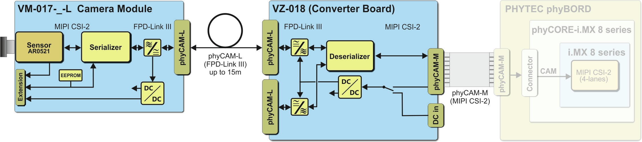
VM-017-_-L Camera with phyCAM-L to phyCAM-M Converter (VZ018) Block Diagram
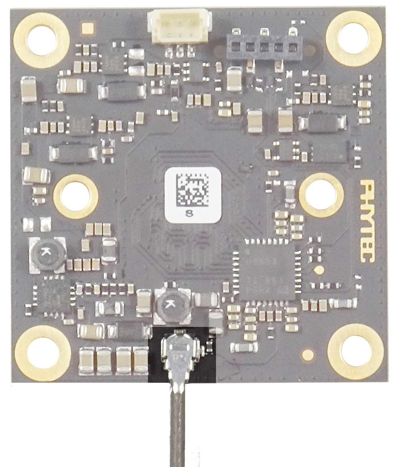
Camera Connector on the VM-017-_-L
The camera board VM-017-_-L is based on the OnSemi camera sensor AR0521. The sensor has a MIPI CSI-2 interface.
On the board, this signal is converted into an FPD-Link III signal and supported at the phyCAM-L interface on the board.
- connect the phyCAM-L coaxial cable at the UMCC Mico coax connector
Camera Connectors on the VZ-018
The phyCAM-L to phyCAM-M bridge VZ-018 had 2 phyCAM-L interfaces and one phyCAM-M interface.
On the board, the FPD-Link III (phyCAM-L) signal is converted into a MIPI CSI-2 signal and supported at the phyCAM-M interface on the board.
- connect the phyCAM-L coaxial cable at the UMCC Mico coax connector Port0 (X9)
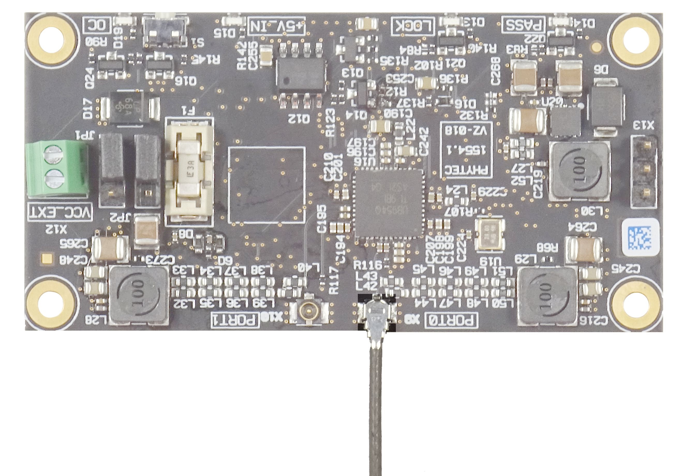
- connect the phyCAM-M FFC cable at the connector X11 with the phyCAM-M connector on the used PHYTEC Embedded Imaging Kit

Open the lock of the 30-pin FFC connector on the camera by lifting the lock upwards.
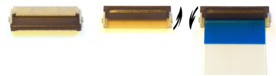
phyCAM-M Flip Lock – FCC Socket Camera Connection
- Plug the 30-pin FFC cable into the FFC socket with the contact surfaces facing downwards until you feel the stop. The reinforcement of the FFC cable (usually highlighted in color) points to the bracket of the socket.
- Lock the FFC socket by carefully pressing it down on the bracket.
Software Support for VM-017 phyCAM-L Starter Kit
To use the VM-017 camera board you need a camera driver for the camera sensor AR0521. Farther is the initialization of the FPD-Link III serializer (TI DS90UB953) and deserializer (TI DS90UB954) necessary. Before the VM-017 camera driver is loaded, the initialization of the bridge must be completed.
For PHYTEC Imaging Kits, these points ready or planned:
- Embedded Imaging Kit Pollux
- Embedded Imaging Kit Polis
- Embedded Imaging Kit Nunki
Please ask PHYTEC for the current state.
If the Kit supports VM-017-_-L, the details to load the camera driver and start of the demo scripts in the kit specific descriptions of the different boards:
- phyCAM with phyBOARD-Pollux iMX 8M Plus Getting Started Guide
- phyCAM with phyBOARD-Polis iMX 8M Mini Getting Started Guide
- phyCAM with phyBOARD-Nunki iMX6 Getting Started Guide
For self-integration with your own embedded controller board and the MIPI CSI-2 interface, we recommend the following documentation:
- TI DS90UB953 datasheet
- TI DS90UB954 datasheet
- OnSemi AR0521 datasheet and register reference (NDA required)
- L-1023e.A0 phyCAM-L VZ-018 phyCAM-M Bridge HW Guide
Revision History
08.07.2021 | L-1030e.A0 | Preliminary Manual |