Gesamtbetrag:
zzgl. Mwst.
Hardware and BSP Manual - phyGATE-Tauri-S i.MX 6UL/ULL Kit (L-1012e.A2)
Table of Contents
Notes about this Manual
Usage
The information in this manual is valid for all standard variants of the phyGATE Tauri-S industrial gateway from PHYTEC Messtechnik GmbH. An overview of all devices and variants to which the descriptions apply can be found inProduct Information.
Before using the document, please check whether it also corresponds to the latest version. The latest version of the manual and other technical documents can be found in the download section of this device's product page at https://www.phytec.de/produkte/fertige-geraete-oem/phygate-tauri/#downloads/.
Warning
For proper installation and safe operation of the device, the operating instructions and in particular the safety instructions contained therein must be carefully read and observed.
Symbols
The manual uses various symbols to indicate helpful and safety-critical notes. Below you will find an explanation of each symbol's meaning.
Warning
This symbol indicates safety-critical information. The warnings must be observed!
Tip
This symbol indicates general notes and helpful information in handling the device.
Safety Instructions and Liability
Intended Use
The phyGATE Tauri-S gateway is designed for monitoring, processing, and communicating machine and sensor data in industrial environments. For data communication, the devices provide various typical industrial interfaces for connection to surrounding devices.
This PHYTEC standard gateway is supplied exclusively as an OEM device by PHYTEC Messtechnik GmbH and requires an adaptation of the operating software for the intended application by the distributor of the device.
Warning
The device must not be used in a manner not specified in this manual to avoid damage to the protection provided by the equipment.
L’appareil ne doit pas être utilisé d'une façon non spécifiée dans ce manuel afin éviter d’endommager la protection fournie par l'équipement.
General Safety Instructions
For commissioning, development work, and assembly, the operating instructions for the device must be used. Knowledge in the following areas is required:
- Electronic circuitry
- Working in electrostatically protected areas
- Accident prevention regulations
- On-site valid rules and regulations for occupational safety
These devices may only be commissioned and installed by adequately qualified personnel with basic electrical knowledge! The device must be handled with care in every phase of its life cycle, in order to prevent destruction by electrostatic discharge or mechanical stress, for example.
Improper modifications and repairs may impair the integrated protective functions and the electromagnetic behavior of the device. This can cause malfunction of the device, interference with connected and surrounding devices, or personal injury. Therefore, interventions on the device may only be carried out by the manufacturer.
Warning
To ensure functional safety, the device must be powered by a SELV/PELV power supply. The gateway must be mounted on a top-hat rail in a fire save control cabinet for permanent use.
Pour garantir la sécurité fonctionnelle, l’appareil doit être alimenté par une alimentation SELV/PELV. Pour une utilisation permanente, la passerelle doit être montée sur un rail profilé chapeau dans une armoire de commande coupe-feu.
Disposal
The operator of these devices must ensure that there is no danger to persons or property in the event of a defect or malfunction of the device. In case of non-repairable defects and device malfunctions, the devices must be taken out of operation and disposed of properly.
Warning
The device must not be disposed of in household waste!

Liability
Improper use and connection of these devices, as well as subsequent processing of these devices (e.g. soldering work on the printed circuit board), lead to exclusion of liability on the part of the manufacturer. Please observe the corresponding information in the operating instructions for proper installation.
Product Information
Product Names and Variants
The phyGATE Tauri-S gateway is available in different variants and expansion stages, which differ in the scope of performance and functions. The following table gives an overview of available variants of the gateway and an explanation for the identification of the article number.
Note
The article numbers have an index ".Ax" where x determines the product revision.
| Parent Product | Article Number | Technical Features |
|---|---|---|
phyGATE Tauri-S Gateway | ||
PB-03513-001.Ax |
| |
PB-03513-002.Ax |
|
Product Overview
phyGATE-Tauri Gateway (25 mm housing)
The phyGATE Tauri-S has several interfaces and controls/displays which are shown in the following figure.
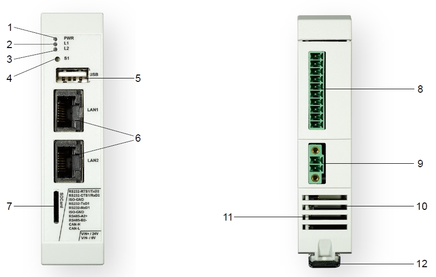
PB-03513-001.Ax | PB-03513-002.Ax | Controls/Displays |
| X | X | 1. Power-LED green |
| X | X | 2. User-LED red (freely configurable) |
| X | X | 3. User-LED yellow (freely configurable) |
| X | X | 4. Button (freely configurable) |
| X | X | 5. USB interface (Typ A) |
| X | X | 6. Ethernet interface (RJ45) |
| X | X | 7. Micro-SD Slot |
| X | X | 8. RS232, RS485, CAN interface (configurable) |
| X | X | 9. Supply connection |
| X | X | 10. Boot-Switch (Concealed, on opposite housing side) |
| X | X | 11. Air vents |
| X | X | 12. Extension interface under a top-hat rail and top-hat rail clip (35mm) |
| X | (13.) SMA antenna connectors | |
| X | (14.) Internal miniPCIe slot (USB only) | |
| X | (15.) SIM card socket |
Nameplate
The nameplate of the phyGATE Tauri-S gateway is located on the side of the housing. Here you will find the essential information about your device.
Technical Data
Warning
All external circuits connected to the phyGATE Tauri-S terminals shall be SELV/PELV.
Electrical Data | |
| min. 12 VDC (-10 %) |
Supply current | max. 380 mA |
| Power adapter type | SELV/PELV |
| Hardware Specification | |
CPU type | NXP i.MX 6ULL Cortex-A7 |
RAM | 512 MB |
eMMC | 8 GB |
Ethernet | 2x 10/100 Mbit/s |
USB | USB 2.0 |
CAN (optional) | max. 1 Mbit/s, isolated |
|
|
| Mass storage | microSD card slot |
| Additional features | TPM chip, Temperature sensor |
RTC | GoldCap for real-time functionality |
| 1x user button |
| Software Specification | |
| Operating system | Linux (Yocto) |
Security Features | Device-Management / Cloud-Update concept |
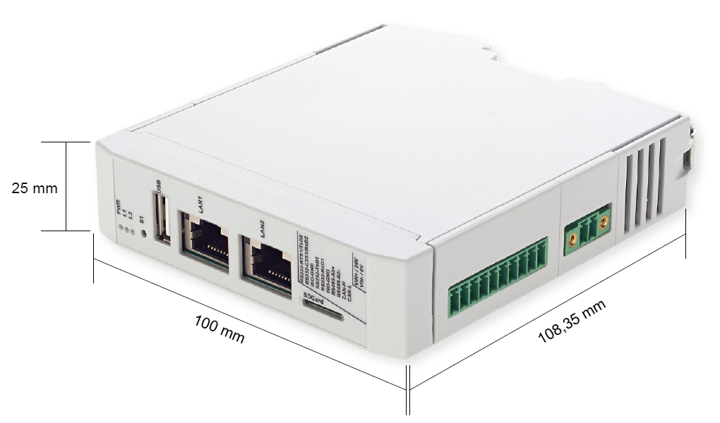
Mechanical Data | |
| Housing type | Phoenix ICS |
Housing material | Polyamide |
| Mounting type | Top-hat rail mounting according to DIN EN 60715 |
IP protection class | max. IP20 |
| 100 mm / 25 mm / 110 mm |
| PB-03513-001.Ax | |
| 100 mm / 50 mm / 110 mm | |
| PB-03513-002.Ax | |
| with customer adapter PCB | |
Weight (depending on variant) | max. 250 g (depending on variant) |
Environmental Data | |
Storage temperature | -20 °C - +70 °C |
| Operating temperature | -20 °C - +60 °C |
Humidity | 10% - 95% non condensing |
| Altitude | max. 2000 m |
| IP protection class control cabinet | min. IP44 |
Package Contents / Accessories
phyGATE Tauri-S Stand-alone device | phyGATE Tauri-S Kit Upgrade |
|---|---|
You'll find the following content within your stand alone phyGATE Tauri-S packaging:
 | The phyGATE Tauri-S Kit-Upgrade for an easy start of development
|
Certification
The phyGATE Tauri-S has been approved for sale and use on the European market and meets the criteria for CE marking according to:
- DIN EN 61000-6-2:2019-11 EMV Interference immunity for industrial areas
- DIN EN 61000-6-3:2020-09 EMV Interference emissions for living area
The CE declaration of conformity for the device can be found online on the product page at https://www.phytec.de/produkte/fertige-geraete-oem/phygate-tauri/.
Warning
Modification of the device, such as adjustments to the software or the use of additional devices in conjunction with the phyGATE Tauri-S Gateway, can influence the electrical properties of the device. In this case, the validity of the CE declaration of conformity is void. For a valid CE marking, a renewed approval by the operator must be carried out in this case.

Technical Dokumentation und Support
Technical documentation for the product can be found on our product page online at https://www.phytec.de/produkte/fertige-geraete-oem/phygate-tauri/#downloads/. If you have any questions or suggestions regarding the product, we look forward to hearing from you:
Technical Product Information
Electrical Connection
The phyGATE Tauri-S gateway has various interfaces for connection to the surrounding infrastructure. The following table lists the connections with the matching mating connectors.
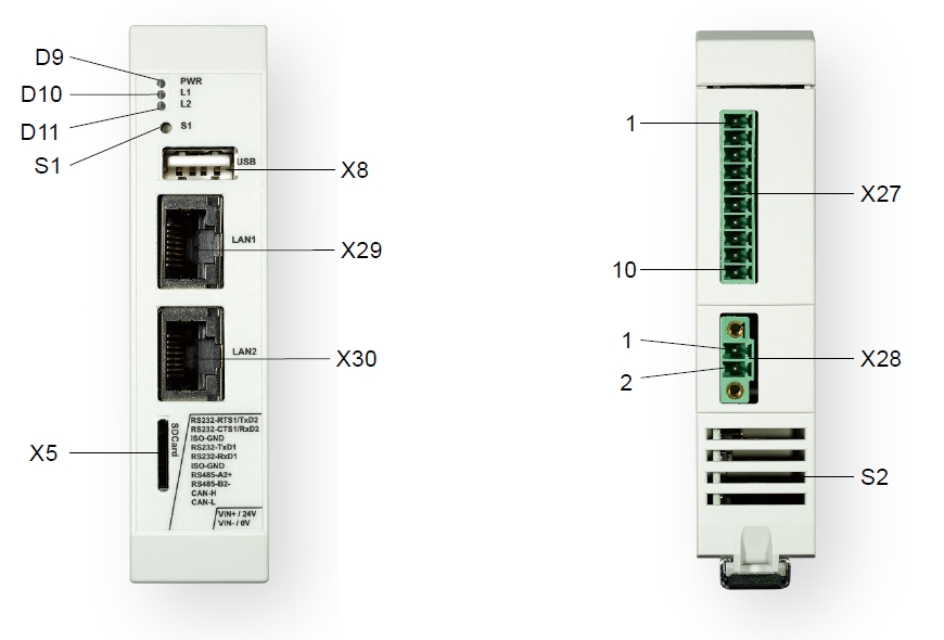
phyGATE Tauri-S Interfaces | |||
Reference | Connection | Device Socket | Mating Connector |
X28 | DC supply | Phoenix MC 1,5/ 2-GF-3,81 | Phoenix MC 1,5/ 2-STF-3,81 Phoenix FMC1.5/2-STF-3.81 |
X29 | Ethernet 1 | RJ45 | RJ45 |
X30 | Ethernet 0 | RJ45 | RJ45 |
X8 | USB | USB-A | USB-A |
X5 | SD Karte | microSD-Slot | microSD-Card |
X27 | RS232 / RS485 / CAN | Phoenix MC 1,5/10G-3,5 | Phoenix MC1,5/10-ST-3,5 Phoenix FMC1.5/10-ST-3.5 |
S1 | User Input Button | --- | --- |
S2 | Boot-Switch | --- | --- |
| D9 | Power-LED (green) | --- | --- |
| D10 / D11 | User-LEDs (red / yellow) | --- | --- |
| (X41 / X23) | Antenna connectors | SMA (female) | SMA (male) |
Pinout of Non-standard Interfaces | |||
| Reference | Connection | Pin | Function |
|
| 1 | +24 VDC |
| 2 | Device GND | ||
|
| 1 | RS232_0_TX |
| 2 | RS232_0_RX | ||
| 3 | GND_ISO | ||
| 4 | RS232_1_TX | ||
5 | RS232_1_RX | ||
6 | GND_ISO | ||
| 7 | RS485_A | ||
| 8 | RS485_B | ||
| 9 | CANH | ||
| 10 | CANL | ||
Warning
Cables with minimum size of AWG22 must be used for connection at the power supply terminal X28. Use copper conductor, only. All connected cables must have a temperature resistance of at least 75 °C.
Warning
For permanently connected equipment: supply wiring requirements, requirements for any external switch or circuit-breaker, and external over-current protections devices, we recommend that the switch or circuit-breaker be near the equipment.
Tip
For the phyGATE Tauri-S variants with RS232 / CAN / RS485, the function of the pins can be configured by the application software.
Warning
To prevent risk of lightning surges, the Ethernet wiring must only be located within the building.
Warning
All signals at connector X27 are galvanically decoupled from the GND reference potential of the board and the supply voltage of the phyGATE Tauri-S.
Mechanical Connection
The phyGATE Tauri-L gateway housing is designed to be mounted on a top-hat rail in the control cabinet. For mounting on the top-hat rail, there is a mounting device on the housing which allows a tool-free and safe mounting on a 35 mm top-hat rail.
Warning
The installation environment, such as the control cabinet in which the device is installed, must meet, as a minimum, the IP44 specifications and must be fireproof.
L'environnement de l’installation du dispositif, comme l'armoire de commande dans laquelle l’appareil est installé, doit répondre, au minimum, aux spécifications IP44 et être ignifuge.
Warning
For intended use, the device must be installed on a 35 mm top-hat rail according to DIN EN 60715.
Pour l'utilisation à laquelle il est destiné, l’appareil doit être monté sur un rail profilé chapeau de 35 mm conformément à la norme DIN EN 60715.
Warning
To prevent malfunction or destruction of the device due to overheating, it is essential to ensure that the ventilation slots are not covered by surrounding components, cables, and other objects. The air must be able to circulate freely around the housing to dissipate heat.
Pour éviter tout dysfonctionnement ou destruction de l’appareil en cas de surchauffe, il est indispensable de s’assurer que les fentes d'aération ne sont pas couvertes par des composants environnants, des câbles et autres objets. L'air doit pouvoir circuler librement autour du boîtier pour dissiper la chaleur.
Getting Started with the phyGATE Tauri-S Gateway
Introduction
To get started easily with your phyGATE Tauri-S device, you'll find a description with the necessary tools and provision of the know-how to work with the Linux Board Support Package (BSP) for the phyCORE-i.MX 6UL/ULL in this chapter. It shows you step by step, how to set up the device for an easy start in development, including:
- essential connection of the device and getting access to the OS
- installing and use the appropriate tools and sources
- building custom kernels
- deploying the OS in order to operate the software and hardware
Tip
All necessary information, software, and other downloads for quick commissioning can be found on the phyGATE Tauri-S product page online at https://www.phytec.de/produkte/fertige-geraete-oem/phygate-tauri/.
Requirements
You'll need the following components to get started quickly with the installation guide of this chapter:
- phyGATE Tauri-S device
- 1x MicroSD Card with prepared prebuilt image
- 1x 24 VDC Mains-Adapter with a mating connector to device supply connector
- 1x LAN cable


Tip
The phyGATE Tauri-S kit upgrade contains all the necessary components to easily start installing the device.
Prepare SD Card for Device Boot
To prepare the MicroSD card for device boot please follow the steps mentioned below.
Tip
If you have a prepared SD card from the phyGATE Tauri-S Kit, this section can be skipped.
If you are using your own SD-Card, you'll have to download the prebuilt image file and burn it to the SD card first:
- Choose the right pre-built image from Phytec-ftp-Server.
- There are two different versions, depending on the interfaces which you want to use. Machine phygate-tauri-imx6ul-1 is for RS232 Handshakes optimized and machine for RS232 and RS485. The following links will take you to the download pages:
- Machine phygate-tauri-imx6ul-1 = NAND-Version → phytec-headless-image-phygate-tauri-imx6ul-1.sdcard
- Machine phygate-tauri-imx6ul-2 = eMMC-Version → phytec-headless-image-phygate-tauri-imx6ul-2.sdcard
- Machine phygate-tauri-imx6ul-3 = eMMC-1GBRAM-Version →phytec-headless-image-phygate-tauri-imx6ul-3.sdcard
- Download the Image file
- Burn Image to the SD-Card (see the description below).
If you are using Windows:
To Burn the Image to the SD-Card, you'll have to use an image burner tool of your choice. The description below is based on the WIN32 Disk Imager Tool.
Please follow the steps below to get your SD card ready with WIN32 Disk Imager:

- Choose the Image File and your microSD device
- Press 'Write' to burn the Image on your microSD card
Warning
Be sure the right Device is selected to avoid damage to other storage devices connected to your computer.
If you are using Linux:
- Open Terminal on Host-System and type the following command to burn the Image:
Host$ sudo dd if=<IMAGENAME>-<MACHINE>.sdcard of=/dev/<your_device> bs=1M conv=fsync status=progress
Booting the Board
Insert the Micro SD Card
To use the SD card as a boot device, you'll have to put the prepared SD-card into the microSD card slot located in the front of the device's housing.
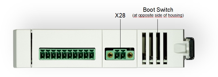
Set Boot Switch
The phyGATE Tauri-S provides a boot switch to choose the boot source of the device. You can choose either eMMC (DIP at position '1') or SD-Card (DIP at position 'ON') as a boot source.
The Switch is located at the opposite side of the housing referenced to the supply connector X28. You can reach the switch in between the vent slots of the housing with help of a small item e.g. a screwdriver to switch the position of the DIP switch.
Powering the Board
The phyGATE Tauri-S has a 2 pin Phoenix Contact MINI COMBICON power connector (counterpart Phoenix Contact FMC 1,5/ 2-STF-3,81). The permissible input voltage is 12 VDC to 36 VDC. A 24 VDC adapter with a minimum current rating of 1A is recommended to supply the board.

After turning the power supply on, the green LED D9 in the device front will light up and the boards will start booting.
Warning
Please note the polarity of the Power connector X28. Make sure that your power adapter is correctly set up to use the polarity as shown in the picture above!
Do not make any electrical changes with the interfaces and cables while the board is connected to power. This is to avoid damage to the device!
Tip
Be aware that as soon as the phyGATE Tauri-S is supplied with power, the SD-Card boot sequence will begin. Ensure that all cables are connected on the board!
Tip
With help of the red user LED in the front of the device housing, you can see if the boot process is running. The LED is flickering during the boot process.
Connecting the OS via SSH
Once the board is done booting, you can connect to the board via Ethernet and SSH. Therefore you need to connect an RJ45 Ethernet cable between the phyGATE Tauri-S and your computer. Make sure that the IP configuration of your computer is configured as follows:
- IP address: 192.168.3.10
- Netmask: 255.255.255.0
Now you are able to log in via SSH. Therefore please use the following login data:
- IP Address: 192.168.3.11 (IP address not evaluated by UL)
- Port: 22
- User: root
- Password: no password
Warning
Login via SSH should only be used for purpose of development. Otherwise, there will be a security risk.
If you are using Windows:
For the SSH connection under Windows, you can use an SSH client of your choice. The description below is based on PuTTY:
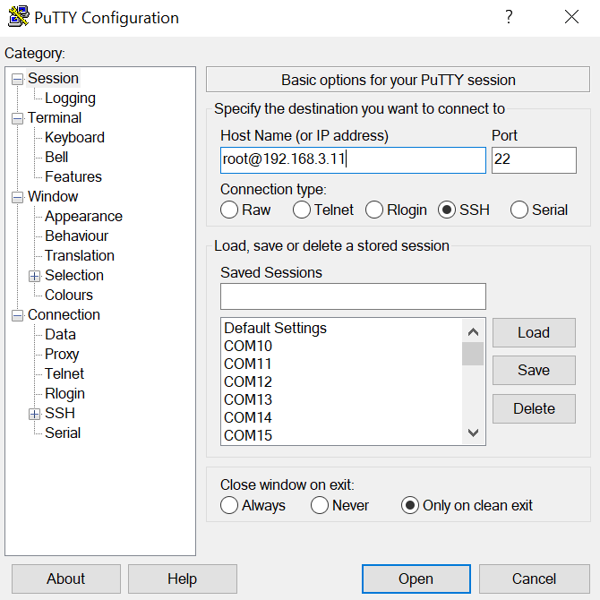
- Configure Host Name as "root@192.168.3.11"
- Press 'Open' to connect the device via SSH
If you are using Linux:
host$ ifconfig <eth-interface> 192.168.3.10 up
host$ ssh root@192.168.3.11
host$
host$ yes
Yogurt Vendor (Phytec Vendor Distribution) 2.6.2 phyGATE-Tauri-imx6ul-2 ttymxc2

phyGATE-Tauri-imx6ul-2 login:
Set up Device Interfaces
Connecting to RS232
The phyGATE-Tauri-S provides up to two RS232 interfaces (RS232_0, RS232_1). From the command line prompt of Linux userspace, you can easily send and receive data over the RS232 interface.
Send:
target$ echo test > /dev/ttymxc1
Receive:
target$ cat /dev/ttymxc1
Connecting to RS485
To use the RS485 interface, it has to be configured before, because the used UART can also be used as a second RS232.
To configure the UART (ttymxc3) as RS485 use the following commands:
target$ echo 121 > /sys/class/gpio/export
target$ echo out > /sys/class/gpio/gpio121/direction
target$ echo 122 > /sys/class/gpio/export
target$ echo out > /sys/class/gpio/gpio122/direction
target$ echo 1 > /sys/class/gpio/gpio121/value
target$ echo 1 > /sys/class/gpio/gpio122/value
After that you are able to configure the interface itself:
target$ stty -F /dev/ttymxc3 115200 -brkint -icrnl -imaxbel -opost -onlcr -isig -icanon -iexten -echo -echoe -echok -echoctl -echoke raw
Use the command echo to send and cat to receives messages:
target$ echo "TEST ttymxc3" > /dev/ttymxc3
target$	cat /dev/ttymxc3
Connecting to CAN
The CAN configuration is automatically done by the daemon systemd. You can send messages with cansend or receive messages with candump:
target$ ip link can0 down
target$ ip link set can0 txqueuelen 10 up type can bitrate 500000 sample-point 0.75 dbitrate 4000000 dsample-point 0.8 fd on
target$ cansend can0 123#ab.cd.ef
target$ candump can0
Connecting to USB
The driver will detect USB-Devices automatically. To mount a USB-Flash for example, use following commands:
target$ mount /dev/disk/by-id/usb_san_disk_0:-part1 /mnt/
target$ cd /mnt
Building the BSP
This section will guide you through the general build process of the i.MX 6UL BSP using the phyLinux script. For more details, see the section phyLinux Documentation in the Yocto Reference Manual. If you want to use our software without phyLinux and the Repo tool managed environment, you can find all Git repositories at:
git://git.phytec.de
Used barebox repository:
git://git.phytec.de/barebox
Our barebox version is based on the mainline bareboxand adds only a few patches which will be sent upstream in the future.
Used Linux kernel repository:
git://git.phytec.de/linux-mainline
Our i.MX 6UL/6ULL Linux kernel is based on the Linux stable kernel. The kernel repository can be found at:
git://git.kernel.org/pub/scm/linux/kernel/git/stable/linux-stable.git
To find out which tag is used for a specific board, look at:
meta-phytec/recipes-bsp/barebox/barebox_*.bb
meta-phytec/recipes-kernel/linux/linux-mainline_*.bb
Get the BSP
Create a fresh project directory:
host$ mkdir ~/yocto
Get the manifest that describes location of the BSP sources:
host$ mkdir ~/tauris
host$ cd ~/tauris
host$ git clone ssh://git@git.phytec.de/meta-pbacd20
host$ cd meta-pbacd20
host$ git checkout -b manifest remotes/origin/manifest
host$ cp <manifest.xml> ~/yocto
Download and run the phyLinux script:
host$ cd ~/yocto
host$ wget https://download.phytec.de/Software/Linux/Yocto/Tools/phyLinux
host$ chmod +x phyLinux
host$ ./phyLinux init -x <manifest.xml>
Basic Set-Up
There are a few important steps which have to be done before the main build process can start.
- To set up the host, see Setting up the Host.
- To set the Git configuration, see Git Configuration.
Finding the Correct Software Platform
To find the correct software and the corresponding machine name for your PHYTEC board, go to i.MX 6UL/ULL BSP Releasesand click on the corresponding BSP release, or refer to the files in the source folder of the BSP:
meta-pbacd20/conf/machine/*.conf
where you can find the platform name to the corresponding product IDs. This information is also displayed by the phyLinux script.
Example: phygate-tauri-imx6ul-1.conf machine configuration file:
#@TYPE: Machine
#@NAME: phygate-tauri-imx6ul-1
#@DESCRIPTION: PHYTEC phyGATE-Tauri i.MX6 ULL, 512MB RAM, NAND
#@ARTICLENUMBERS: PB-03513-001.Ax, PCL-063-23900CI.A0
Machine phygate-tauri-imx6ul-1.conf represents the phyGate-Tauri with PCL-063-23900CI.A0 phyCORE-i.MX 6UL.
Selecting a Software Platform
To select the correct SOC, BSP version, and platform, call:
host$ ./phyLinux init
It is also possible to pass this information directly using command line parameters:
host$ ./phyLinux init -p imx6ul -r PD19.1.0
Please read the section Initialization for more information.
Starting the Build Process
Refer to the section Start the Build.
BSP Images
All images generated by Bitbake are deployed to yocto/build/deploy/images/<machine>.
As an example, the following list shows all files generated for the i.MX 6ULL SOC, phygate-tauri-imx6ul-1 machine:
- Barebox: barebox.bin
- Barebox configuration: barebox-defconfig
- Kernel: zImage
- Kernel device tree file: imx6ull-phygate-tauri-nand.dtb
- Kernel configuration: zImage.config
- Root filesystem: phytec-headless-image-phygate-tauri-imx6ul-1.tar.gz, phytec-headless-image-phygate-tauri-imx6ul-1.ubifs
- SD card image: phytec-headless-image-phygate-tauri-imx6ul-1.sdcard
Booting the System
The default boot source for the i.MX 6UL/6ULL modules like phyCORE-i.MX 6UL or phyCORE-i.MX 6ULL is the NAND flash. The easiest way to get started with your freshly created images is by writing them to an SD card and setting the boot configuration accordingly. For information on how to set the correct boot configuration, refer to the corresponding hardware manual for your PHYTEC board.
Booting from NAND Flash
NAND is the default boot source. To update the NAND Flash software, see Updating the Software.
Note
On BSP version PD19.1.0, there is a software issue about factory bad block detection, in which only 25% of the factory bad blocks are detected correctly and marked as such. Any I/O operation on the unmarked bad blocks will lead to an error. Please read the BSP Release Notes for more information. This issue is fixed on PD19.1.1.
Booting from SD Card
Booting from SD card is useful in several situations, for example, if the board does not start due to a damaged bootloader. To boot from SD card, the SD card must be formatted in a special way as the i.MX 6UL/6ULL ROM code does not use file systems. Instead, it expects the bootloader at a fixed location on the SD card.
There are two ways to create a bootable SD card. You can either use:
- a single prebuild SD card image, or
- the four individual images (barebox-, kernel- and device tree image, and root filesystem)
Using a Single, Prebuild SD Card Image
The first option is to use the SD card image built by Yocto. This image has the ending *.sdcard and can be found under build/deploy/images/<MACHINE>/<IMAGENAME>-<MACHINE>.sdcard. It contains all BSP files in already correctly formatted image and can be easily copied to the SD card by using the single Linux command dd.
You can also find ready-to-use *.sdcard images on our FTP server.
Warning
To create your bootable SD card with the dd command you must have root privileges. Because of that, you must be very careful when selecting the destination device for the dd command! All files on the selected destination device will be erased immediately without any further query! Consequently, having selected the wrong device can also erase your hard drive!
To create your bootable SD card, you must first find the correct device name and possible partitions of your SD card. Then unmount the partitions before you start copying the image to the SD card.
- In order to get the correct device name first remove your SD card and execute ls /dev.
- Next, insert your SD card and execute ls /dev again.
- Compare the two outputs to find the new device name(s) listed in the second output. These are the device names of the SD card (device and partitions if the SD card is formatted).
- In order to verify the device names found, execute the command dmesg. Within the last lines of its output, you should also find the device names, for example, sde (depending on your system).
Now that you have the device name /dev/<your_device> (e.g. /dev/sde) you can also recognize the partitions which must be unmounted if the SD card is formatted. In this case, you will also find /dev/<your_device> with an appended number (e.g. /dev/sde1) in the output. These represent the partition(s) to be unmounted.
- Unmount all partitions:
host$ umount /dev/<your_device><number>
- After having unmounted all devices with an appended number (<your_device><number>), you can create your bootable SD card:
host$ sudo dd if=<IMAGENAME>-<MACHINE>.sdcard of=/dev/<your_device> bs=1MB conv=fsync
using the device name (<your_device>) without appended number (e.g. sde) which stands for the whole device.
The parameter conv=fsync forces a sync operation on the device before dd returns. This ensures that all blocks are actually written to the SD card and do not remain in the memory.
Using Four Individual Images (barebox-, kernel- and device tree image, and root filesystem)
Instead of using the single prebuild SD card image, you can use the barebox, kernel, and device tree image together with the root filesystem separately to manually create a bootable SD card.
For this method, a new card must be set up with 2 partitions and 8 MB of free space at the beginning of the card. Use the following procedure with fdisk under Linux:
- Create a new FAT partition with partition id C. When creating the new partition, you must leave 8 MB of free space at the beginning of the card. When you go through the process of creating a new partition, fdisk lets you specify where the first sector starts. During this process, fdisk will tell you where the first sector on the disk begins. If, for example, the first sector begins at 2048, and each sector is 512 bytes. 8 MB / 512 bytes = 16384 sectors, which means your first sector should begin at 18432 to leave 8 MB of free space. The size of the FAT partition only needs to be big enough to hold the zImage which is only a few megabytes. To be safe we, recommend a size of 64 MB.
- Create a new Linux partition with partition id 83. Make sure you start this partition after the last sector of partition 1! By default, fdisk will try to use the first partition available on the disk, which in this example is 1000. However, this is our reserved space! You must use the remaining portion of the card for this partition.
- Write the new partition to the SD card and exit fdisk.
Example:
- Type:
host$ sudo fdisk -l /dev/sdc
You will receive:
Disk /dev/sde: 3,8 GiB, 4025483264 bytes, 7862272 sectors
Units: sectors of 1 * 512 = 512 bytes
Sector size (logical/physical): 512 bytes / 512 bytes
I/O size (minimum/optimal): 512 bytes / 512 bytes
Disklabel type: dos
Disk identifier: 0xef6c9559

Device     Boot  Start     End Sectors  Size Id Type
/dev/sde1        18432  149503  131072   64M  c W95 FAT32 (LBA)
/dev/sde2       149504 7862271 7712768  3,7G 83 Linux
Remove and reinsert the card. Otherwise, Linux will not recognize the new partitions created in the previous step. Create a file system on the partitions with (replace 'sde' with your device):
host$ sudo mkfs.vfat /dev/sde1
host$ sudo mkfs.ext4 -L "rootfs" /dev/sde2
Now the images need to be copied to the SD card. Write the bootloader in front of the first partition (replace 'sde' with your device):
host$ sudo dd if=barebox.bin of=/dev/sde bs=512 skip=2 seek=2 conv=fsync
Mount the first partition (vfat) and copy the zImage and oftree file to it:
host$ sudo mount /dev/sd<X>1 /mnt
Warning
Make sure that the images are named as zImage (kernel) and oftree (devicetree), as the bootloader expects them exactly like that.
In case you want to boot the whole Linux from SD card, mount the ext4 partition. Then untar <IMAGENAME>-<MACHINE>.tar.gz rootfs image to it:
host$ sudo mount /dev/sd<X>2 /media
host$ sudo tar zxf <IMAGENAME>-<MACHINE>.tar.gz -C /media/
Do not forget to properly unmount the SD card:
host$ sudo umount /media
Booting from eMMC
On phyCORE-i.MX 6UL/6ULL, eMMC can be equipped instead of NAND flash. For these boards, eMMC is the default boot source. To update the software of the eMMC, see Updating the Software.
Booting the Kernel from Network
Booting from the network means loading the kernel and device tree over TFTP. The bootloader itself must already be loaded from any other boot device available.
Development Host Preparations
On the development host, a TFTP server must be installed and configured. The following tools will be needed to boot the Kernel from Ethernet:
- A TFTP server and
- An optional tool for starting/stopping a service (xinetd).
For Ubuntu, install:
host$ sudo apt-get install tftpd-hpa xinetd
After the installation, there are two ways to configure the TFTP server:
- As a standalone daemon
- Controlled and handled by xinetd
First, create a directory to store the TFTP files:
host$ sudo mkdir /tftpboot
host$ sudo chmod -R 777 /tftpboot
host$ sudo chown -R nobody /tftpboot
Then copy your BSP image files to this directory. You also need to configure a static IP address for the appropriate interface. The default IP address of the PHYTEC evaluation boards is 192.168.3.11 (IP address not evaluated by UL) . So setting 192.168.3.10 with netmask 255.255.255.0 as a host address is a good choice.
Configure TFTP as a stand alone daemon
Create or edit /etc/default/tftpd-hpa:
# /etc/default/tftpd-hpa

TFTP_USERNAME="nobody"
TFTP_DIRECTORY="/tftpboot"
TFTP_ADDRESS="192.168.3.10:69"
TFTP_OPTIONS="-s -c"
Set TFTP_DIRECTORY to your TFTP server root directory
Set TFTP_ADDRESS to the host address the server is listening to (set to 0.0.0.0:69 to listen to all local IPs)
Set TFTP_OPTIONS, following command, shows the available options:
host$ man tftpd
Restart the services to pick up the configuration changes:
host$ sudo service tftpd-hpa restart
Configure TFTP as xinetd service:
To run the TFTP server with xinetd, the standalone daemon first needs to be disabled:
host$ sudo systemctl disable tftpd-hpa
host$ sudo systemctl stop tftpd-hpa
If necessary, edit or create /etc/xinetd.d/tftp:
service tftp
{
	protocol = udp
	port = 69
	socket_type = dgram
	wait = yes
	user = root
        server = /usr/sbin/in.tftpd
	server_args = -s /tftpboot
	disable = no
}
server_args holds the options and the TFTP server root directory
Reload the services to pick up the configuration changes:
sudo /etc/init.d/xinetd reload
After the installation of the TFTP server, an NFS server needs to be installed, too. The NFS server is not restricted to a certain file system location, so all we have to do on most distributions is modify the file /etc/exports and export our root filesystem to the embedded network. For that, append /etc/exports:
/home/<user>/<rootfspath> 192.168.3.11/255.255.255.0(rw,no_root_squash,sync,no_subtree_check)
and adapt it to your local needs, where <user> must be replaced with your home directory name and the <rootfspath> can be set to a folder which contains an extracted rootfs tar.gz image.
Updating from SD Card
To update the software from SD card, one needs an SD card that holds all required images (barebox, kernel, devicetree and root filesystem). Using an SD card that was flashed with the .sdcard image from Yocto out of the box is not possible since the FAT partition holding the kernel and devicetree image is not big enough to hold the root filesystem images.
A new partitioning scheme is created for the SD card. The SD card will hold the barebox in 8 MiB unpartitioned space at the first sectors to still be able to boot from this SD card and following that a FAT partition which will hold all required images (including a copy of the barebox image).
Use the following procedure with fdisk under Linux:
- First, delete all existing partitions on the disk and then create a new primary FAT partition with partition id C. When creating the new partition you must leave 8 MB of free space at the beginning of the card. When you go through the process of creating a new partition, fdisk lets you specify where the first sector starts. With the command F on an unpartitioned disk, fdisk tells you where the first sector on the disk begins. If, for example, the first sector begins at 2048 and each sector is 512 bytes, then 8 MB / 512 bytes = 16384 sectors. Therefore, your first sector should begin at 18432 to leave 8 MB of free space. The size of the FAT partition needs to be at least big enough to hold all required images. The partition can easily cover the rest of the SD card.
- Remove and reinsert the card. Otherwise, Linux will not recognize the new partitions created in the previous step.
- Create a file system on the partition with (replace 'sde' with your device):
host$ sudo mkfs.vfat /dev/sde1
Now write the barebox in front of the partition (replace 'sde' with your device):
host$ sudo dd if=barebox.bin of=/dev/sde bs=512 skip=2 seek=2 conv=fsync
Mount the FAT partition and copy all required images to the partition (replace 'sde' with your device):
host$ sudo mount /dev/sde1 /mnt
After copying unmount the FAT partition and insert the SD card into your board:
host$ sudo umount /mnt
To update i.MX 6UL/6ULL board from SD card, the SD card used for updating must be mounted after the board is powered and the boot sequence is stopped on the bootloader prompt. If the board is booted from SD card, the card is already mounted automatically under /mnt/mmc/. Otherwise, mount the SD card in the barebox with:
bootloader$ detect mmc0
It is then also mounted under /mnt/mmc/ if it was partitioned as described above. In any other case, the partition needs to be mounted manually.
Updating the bootloader from Linux Userspace
It is possible to update the barebox bootloader from within the booted Linux userspace. This can only be done if certain specifications have been met.
Updating NAND Flash bootloader from Linux Userspace
To update the barebox on the NAND Flash from within Linux Userspace, the kobs-ng tool is used. It implements the same failsafe update mechanism that is used with the barebox-update tool in the barebox. The following command requires the new barebox image to be copied to the target.
To update the barebox on the target type:
target$ kobs-ng init --search_exponent=1 barebox.bin
We also recommend erasing the environment of the old barebox. Otherwise, the new barebox will still use the old environment.
target$ flash_erase /dev/mtd1 0 0
After a reboot or power cycle, the new barebox will be used.
Updating eMMC bootloader from Linux Userspace
To update the bootloader on the eMMC from within Linux userspace, the dd command is used. This is similar to pregramming the bootloader to an SD card (see Booting from SD Card).
Some precautions need to be taken when updating the bootloader on the eMMC. The i.MX 6UL/6ULL ROM code expects the bootloader at a specific offset from the beginning of the eMMC. In front of that lies the partitioning table of the filesystem which follows the bootloader. So we have to make sure not to overwrite the partitioning table. Copying the bootloader to the eMMC can be achieved with:
target$ dd if=barebox.bin of=/dev/mmcblk1 bs=512 skip=2 seek=2 conv=fsync
We also recommend erasing the environment of the old barebox. Otherwise the new barebox will still use the old environment:
target$ dd if=/dev/zero of=/dev/mmcblk0 bs=128k count=1 seek=7
After a reboot or power cycle, the new barebox will be used.
RAUC
Since the rocko release, the RAUC (Robust Auto-Update Controller) mechanism support has been added to Yogurt. It controls the procedure of updating a device with new firmware. This includes updating Linux kernel, Device Tree, and rootfs. It does not update the bootloader. For more information about RAUC, see https://rauc.readthedocs.io/en/latest/.
RAUC uses the barebox bootchooser and state framework (see Barebox Bootchooser and Barebox State-Framework for more information). It can be used in different update scenarios. Have a look at the use cases below and the example setup used in the BSP.
RAUC on i.MX 6UL/6ULL
With the BSP-Yocto-i.MX6UL-PD19.10 BSP release, RAUC (Robust Auto-Update Controller) can be used with NAND flash. It is not enabled by default but our example can be configured and activated with the instructions shown below. RAUC can be used in different update scenarios. As an example, we configured the BSP to use an A-B setup with two redundant systems.

The partition layout is defined in the /etc/rauc/system.conf file. Shown here is the system_nand.conf from meta-yogurt used for our example setup:
[system]
compatible=@MACHINE@
bootloader=barebox
mountprefix=/mnt/rauc

[handlers]
pre-install=/usr/bin/rauc_downgrade_barrier.sh

[keyring]
path=ca.cert.pem

#System A
[slot.rootfs.0]
device=/dev/ubi0_2
type=ubifs
bootname=system0

[slot.kernel.0]
device=/dev/ubi0_0
type=ubivol
parent=rootfs.0

[slot.dtb.0]
device=/dev/ubi0_1
type=ubivol
parent=rootfs.0

#System B
[slot.rootfs.1]
device=/dev/ubi0_5
type=ubifs
bootname=system1

[slot.kernel.1]
device=/dev/ubi0_3
type=ubivol
parent=rootfs.1

[slot.dtb.1]
device=/dev/ubi0_4
type=ubivol
parent=rootfs.1
There is no configuration for the barebox since a barebox update with RAUC is not supported.
Warning
Updates with RAUC use an openSSL certificate to verify the validity of an image. The BSP includes a certificate which can be used for development. In a productive system, however, it is highly recommended to use a self-created key and certificate.
Creating RAUC Bundles
To update your system with RAUC, a RAUC bundle (.raucb) needs to be created. It contains all required images and scripts for the update and a RAUC manifest.raucm that describes the content of the bundle for the RAUC update on the target. The BSP includes a Yocto target that lets you build a RAUC bundle from your Yocto build.
To create the bundle with Yocto, run:
host$ bitbake phytec-qt5demo-bundle
in your Yocto build.
This results in the creation of a .raucb bundle file in the deploy/images/<machine-name>/phytec-qt5demo-bundle-<machine-name>.raucb file which can be used for an update described in the next chapter. There is no need to create a manifest.raucm manually as it is created automatically during the build of the bundle. But as a reference, the created manifest would look something like:
[update]
compatible=phygate-tauri-imx6ul-1
version=r1
description=PHYTEC rauc bundle based on BSP-Yocto-i.MX6UL-PD19.1.0
build=20190521073744

[image.rootfs]
sha256=586fe06c3d61ff04023a8cb3ddd6d246f8031ef0a05b1ed25213f7db8897ff2b
size=130023424
filename=phytec-headless-image-phygate-tauri-imx6ul-1.ubifs
[image.kernel]
sha256=1a184e5356267277211eb690a151977d5f872b4ae8f0661ac5d963b4e83efdfa
size=6725712
filename=zImage-phygate-tauri-imx6ul-1.bin
[image.dtb]
sha256=2102512a05e37ba78e8dba06553be2f1c686e85acafbe5efd44e48c554b3f6db
size=34242
filename=imx6ull-phygate-tauri-nand.dtb
For more information about the manifest format, see https://rauc.readthedocs.io/en/latest/reference.html#manifest.
Tip
Currently, there is a bundle target for the phytec-qt5demo-image (phytec-qt5demo-bundle) and the phytec-headless-image (phytec-headless-bundle).
Update NAND Flash with RAUC
To update the NAND flash with RAUC, the RAUC bundle file previously created first needs to be copied to the board or to a memory device that can be mounted in Linux. One way is to copy the bundle file with scp, but make sure that there is enough space left on the board's filesystem. To do this, boot the target board to Linux and connect it via Ethernet to your host PC.
On the host, run:
host$ scp phytec-qt5demo-bundle-phygate-tauri-imx6ul-1.raucb root@192.168.3.11:/home/root/
On the target, you can verify the bundle:
target$ rauc info phytec-qt5demo-bundle-phygate-tauri-imx6ul-1.raucb
and get output similar to this:
rauc-Message: Reading bundle: /home/root/phytec-qt5demo-bundle-phygate-tauri-imx6ul-1.raucb
rauc-Message: Verifying bundle...
Compatible:     'phygate-tauri-imx6ul-1'
Version:        'r0'
Description:    'PHYTEC rauc bundle based on BSP-Yocto-i.MX6UL-PD19.1.0'
Build:          '20190521073744'
Hooks:          ''
3 Images:
(1)     phytec-headless-image-phygate-tauri-imx6ul-1.ubifs
        Slotclass: rootfs
        Checksum:  586fe06c3d61ff04023a8cb3ddd6d246f8031ef0a05b1ed25213f7db8897ff2b
        Size:      130023424
        Hooks:
(2)     zImage-phygate-tauri-imx6ul-1.bin
        Slotclass: kernel
        Checksum:  1a184e5356267277211eb690a151977d5f872b4ae8f0661ac5d963b4e83efdfa
        Size:      6725712
        Hooks:
(3)     imx6ull-phygate-tauri-nand.dtb
        Slotclass: dtb
        Checksum:  2102512a05e37ba78e8dba06553be2f1c686e85acafbe5efd44e48c554b3f6db
        Size:      34242
        Hooks:
0 Files

Certificate Chain:
 0 Subject: /O=PHYTEC Messtechnik GmbH/CN=PHYTEC Messtechnik GmbH Development-1
   Issuer: /O=PHYTEC Messtechnik GmbH/CN=PHYTEC Messtechnik GmbH PHYTEC BSP CA Development
   SPKI sha256: E2:47:5F:32:05:37:04:D4:8C:48:8D:A6:74:A8:21:2E:97:41:EE:88:74:B5:F4:65:75:97:76:1D:FF:1D:7B:EE
   Not Before: Jan  1 00:00:00 1970 GMT
   Not After:  Dec 31 23:59:59 9999 GMT
 1 Subject: /O=PHYTEC Messtechnik GmbH/CN=PHYTEC Messtechnik GmbH PHYTEC BSP CA Development
   Issuer: /O=PHYTEC Messtechnik GmbH/CN=PHYTEC Messtechnik GmbH PHYTEC BSP CA Development
   SPKI sha256: AB:5C:DB:C6:0A:ED:A4:48:B9:40:AC:B1:48:06:AA:BA:92:09:83:8C:DC:6F:E1:5F:B6:FB:0C:39:3C:3B:E6:A2
   Not Before: Jan  1 00:00:00 1970 GMT
   Not After:  Dec 31 23:59:59 9999 GMT
To check the current state of the system, run:
target$ rauc status
and get output similar to:
Compatible:  phygate-tauri-imx6ul-1
Variant:
Booted from: system0
Activated:   rootfs.0 (system0)
slot states:
  dtb.1: class=dtb, device=/dev/ubi0_4, type=ubivol, bootname=(null)
      state=inactive, description=, parent=rootfs.1, mountpoint=(none)
  rootfs.0: class=rootfs, device=/dev/ubi0_2, type=ubifs, bootname=system0
      state=booted, description=, parent=(none), mountpoint=(none)
      boot status=good
  kernel.1: class=kernel, device=/dev/ubi0_3, type=ubivol, bootname=(null)
      state=inactive, description=, parent=rootfs.1, mountpoint=(none)
  rootfs.1: class=rootfs, device=/dev/ubi0_5, type=ubifs, bootname=system1
      state=inactive, description=, parent=(none), mountpoint=(none)
      boot status=good
  kernel.0: class=kernel, device=/dev/ubi0_0, type=ubivol, bootname=(null)
      state=active, description=, parent=rootfs.0, mountpoint=(none)
  dtb.0: class=dtb, device=/dev/ubi0_1, type=ubivol, bootname=(null)
      state=active, description=, parent=rootfs.0, mountpoint=(none)
To update the currently inactive system with the downloaded bundle, run:
target$ rauc install phytec-headless-bundle-phygate-tauri-imx6u1-6.raucb
and reboot afterward:
target$ reboot
Tip
When you update from a USB stick, make sure to remove the stick after a successful update before reboot. If not, an atomatic update will be started after each boot. This due to the "Automatic Update from USB Flash Drive example" you can find below.
With success of the update, RAUC automatically switches the active system to the newly updated system. Now during reboot, RAUC counts the boot attempts of the kernel and if it fails more often than specified in the state framework of the system, RAUC switches back to the old system and marks the new system as bad. If the boot attempt to the kernel is successful, the new system is marked as good and now the old system can be updated with the same instructions. After two successful rauc install and reboot, both systems are updated.
Change the Active Boot Slot
It is possible to switch the active system manually:
target$ rauc status mark-active other
Now after a reboot or power cycle, the kernel starts from the alternate system.
Use Case 1: Automatic Update from USB Flash Drive with RAUC
One of the most prominent use cases for RAUC might be an automatic update system from a USB flash drive. This use case is implemented in the BSP as a reference example. We combine only standard Linux mechanisms with RAUC to build the system. The kernel notifies udev when a device gets plugged into the USB port. We use a custom udev rule to trigger a systemd service when this event happens.
10-update-usb.rules udev rule:
KERNEL!="sd[a-z][0-9]", GOTO="media_by_label_auto_mount_end"

# Trigger systemd service
ACTION=="add", TAG+="systemd", ENV{SYSTEMD_WANTS}="update-usb@%k.service"

# Exit
LABEL="media_by_label_auto_mount_end"
The service automounts the USB flash drive and notifies the application. update-usb@.service systemd service file:
[Unit]
Description=usb media RAUC service
After=multi-user.target
Requires=rauc.service

[Service]
Type=oneshot
Environment=DBUS_SESSION_BUS_ADDRESS=unix:path=/run/dbus/system_bus_socket
ExecStartPre=/bin/mkdir -p /media/%I
ExecStartPre=/bin/mount -t auto /dev/%I /media/%I
ExecStart=/usr/bin/update_usb.sh %I
ExecStop=/bin/umount -l /media/%I
ExecStopPost=-/bin/rmdir /media/%I
In our reference implementation, we simply use a bash script for the application logic. update_usb.sh update script:
#!/bin/sh

MOUNT=/media/$1

NUMRAUCM=$(find ${MOUNT}/*.raucb -maxdepth 0 | wc -l)

[ "$NUMRAUCM" -eq 0 ] && echo "${MOUNT}*.raucb not found" && exit
[ "$NUMRAUCM" -ne 1 ] && echo "more than one ${MOUNT}/*.raucb" && exit

rauc install $MOUNT/*.raucb
if [ "$?" -ne 0 ]; then
	echo "Failed to install RAUC bundle."
else
	echo "Update successful."
fi
exit $?
The update logic could be integrated into an application by using systemd's D-Bus API. RAUC also does not need to be called by its command line interface but can be integrated with D-Bus.
Tip
RAUC features a D-Bus API interface (see https://rauc.readthedocs.io/en/latest/using.html#using-the-d-bus-api).
Use Case 2: Security measurement: downgrade barrier
As a second reference example, we will implement a security mechanism: a downgrade barrier. When you detect a security vulnerability on your system, you will fix it and update your system. The systems with the new software will now be secure again. If an attacker gets ahold of the old software update bundle, which has still a valid signature, the attacker might have the possibility to install the old software and still take advantage of the previously fixed security vulnerability. To prevent this from happening, you could revoke the update certificate for every single update and create a new one. This might be difficult to handle, depending on the environment. A simpler solution would be to allow updates only in one direction using a version check.
rauc_downgrade_barrier.sh in meta-yogurt:
#!/bin/sh

VERSION_FILE=/etc/rauc/downgrade_barrier_version
MANIFEST_FILE=${RAUC_UPDATE_SOURCE}/manifest.raucm

[ ! -f ${VERSION_FILE} ] && exit 1
[ ! -f ${MANIFEST_FILE} ] && exit 2

VERSION=`cat ${VERSION_FILE} | cut -d 'r' -f 2`
BUNDLE_VERSION=`grep "version" -rI ${MANIFEST_FILE} | cut -d 'r' -f 3`

# check from empty or unset variables
[ -z "${VERSION}" ] && exit 3
[ -z "${BUNDLE_VERSION}" ] && exit 4

# developer mode, allow all updates if version is r0
[ ${VERSION} -eq 0 ] && exit 0

# downgrade barrier
if [ ${VERSION} -gt ${BUNDLE_VERSION} ]; then
        echo "Downgrade barrier blocked rauc update! CODE5\n"
else
        exit 0
fi
exit 5
The script is installed on the target but it is not activated. You need to remove the developer mode line in the script to activate it.
How to setup RAUC for your Machine
First, you need to add the state framework configuration to the barebox device tree. Check out the BSP Customizationchapter in the Yocto reference manual. You have to include the imx6ul-phytec-state.dtsi file to your barebox device tree by adding
#include imx6ul-phytec-state.dtsi
to the includes. Afterward, rebuild the image
Warning
Be aware that by adding the state framework configuration, the EEPROM is partly occupied and can no longer be used for user-specific purposes.
The following device tree snippet shows the state framework configuration used with the BSP. As you can see, the EEPROM is used as a backend for the state information.
/ {
        aliases {
                state = &state;
        };

        state: imx6ul_phytec_boot_state {
                magic = <0x883b86a6>;
                compatible = "barebox,state";
                backend-type = "raw";
                backend = <&backend_update_eeprom>;
                backend-stridesize = <54>;
                status = "disabled";

                #address-cells = <1>;
                #size-cells = <1>;
                bootstate {
                        #address-cells = <1>;
                        #size-cells = <1>;
                        last_chosen {
                                reg = <0x0 0x4>;
                                type = "uint32";
                        };
                        system0 {
                                #address-cells = <1>;
                                #size-cells = <1>;
                                remaining_attempts {
                                        reg = <0x4 0x4>;
                                        type = "uint32";
                                        default = <3>;
                                };
                                priority {
                                        reg = <0x8 0x4>;
                                        type = "uint32";
                                        default = <21>;
                                };
                                ok {
                                        reg = <0xc 0x4>;
                                        type = "uint32";
                                        default = <0>;
                                };
                        };
                        system1 {
                                #address-cells = <1>;
                                #size-cells = <1>;
                                remaining_attempts {
                                        reg = <0x10 0x4>;
                                        type = "uint32";
                                        default = <3>;
                                };
                                priority {
                                        reg = <0x14 0x4>;
                                        type = "uint32";
                                        default = <20>;
                                };
                                ok {
                                        reg = <0x18 0x4>;
                                        type = "uint32";
                                        default = <0>;
                                };
                        };
                };
        };
};

&eeprom {
        partitions {
                compatible = "fixed-partitions";
                #size-cells = <1>;
                #address-cells = <1>;
                backend_update_eeprom: state@0 {
                        reg = <0x0 0x100>;
                        label = "update-eeprom";
                };
        };
};
The next steps do not require a rebuild of the image and can be performed on a running system. To be able to boot from two systems alternately, the bootchooser needs to be aware of the state framework configuration. Also, two new boot scripts have to be created for system0 and system1 of the A-B system. To fulfill these requirements, boot your board and stop the boot process in the barebox.
Create the NAND boot script for system0 with:
bootloader$ edit /env/boot/system0
and insert the following to the file:
#!/bin/sh

[ -e /env/config-expansions ] && /env/config-expansions

[ ! -e /dev/nand0.root.ubi ] && ubiattach /dev/nand0.root

global.bootm.image="/dev/nand0.root.ubi.kernel0"
global.bootm.oftree="/dev/nand0.root.ubi.oftree0"

global.linux.bootargs.dyn.root="root=ubi0:root0 ubi.mtd=root rootfstype=ubifs"
Write the file by pressing CTRL-D and run:
bootloader$ saveenv
to save the environment. Create the NAND boot script for system1 with:
bootloader$ edit /env/boot/system1
and insert the following to the file:
#!/bin/sh

[ -e /env/config-expansions ] && /env/config-expansions

[ ! -e /dev/nand0.root.ubi ] && ubiattach /dev/nand0.root

global.bootm.image="/dev/nand0.root.ubi.kernel1"
global.bootm.oftree="/dev/nand0.root.ubi.oftree1"

global.linux.bootargs.dyn.root="root=ubi0:root1 ubi.mtd=root rootfstype=ubifs"
Write the file by pressing CTRL-D and run:
bootloader$ saveenv
to save the environment. Run the following commands to create the required bootchooser non-volatile environment variables:
bootloader$ nv bootchooser.state_prefix=state.bootstate
bootloader$ nv bootchooser.system0.boot=system0
bootloader$ nv bootchooser.system1.boot=system1
bootloader$ nv bootchooser.targets="system0 system1"
To simplify the initial partitioning and update of the NAND flash, two script are used. The /env/bin/rauc_init_nand script is used to format and partition the NAND flash. Create this script:
bootloader$ edit /env/bin/rauc_init_nand
and insert the following to the file (adapt the root filesystem sizes to the size of your NAND flash. Remember, the barebox, barebox-environment, kernel, and device tree use space too!):
echo "Create NAND partitions using rauc with backup system"
ubiformat -q -y /dev/nand0.root
ubiattach /dev/nand0.root
#Hold the following order or change the /dev/ubi0_X enumeration in /etc/rauc/system.conf
ubimkvol -t static /dev/nand0.root.ubi kernel0 16M
ubimkvol -t static /dev/nand0.root.ubi oftree0 1M
#For 512MB NANDs (otherwise other partition sizes)
ubimkvol -t dynamic /dev/nand0.root.ubi root0 236M
ubimkvol -t static /dev/nand0.root.ubi kernel1 16M
ubimkvol -t static /dev/nand0.root.ubi oftree1 1M
ubimkvol -t dynamic /dev/nand0.root.ubi root1 236M
ubidetach /dev/nand0.root
Write the file by pressing CTRL-D and run:
bootloader$ saveenv
to save the environment. The /env/bin/rauc_flash_nand_from_tftp script is used to update the kernel, device tree, and root filesystem of both systems with images from network. To create it, use:
bootloader$ edit /env/bin/rauc_flash_nand_from_tftp
and insert the follwing to the file:
echo "Initialize NAND flash for rauc from TFTP"
[ ! -e /dev/nand0.root.ubi ] && ubiattach /dev/nand0.root
ubiupdatevol /dev/nand0.root.ubi.kernel0  /mnt/tftp/zImage
ubiupdatevol /dev/nand0.root.ubi.kernel1 /mnt/tftp/zImage
ubiupdatevol /dev/nand0.root.ubi.oftree0 /mnt/tftp/oftree
ubiupdatevol /dev/nand0.root.ubi.oftree1 /mnt/tftp/oftree
# Update rootfs image name as needed
cp /mnt/tftp/root.ubifs /dev/nand0.root.ubi.root0
cp /mnt/tftp/root.ubifs /dev/nand0.root.ubi.root1
ubidetach /dev/nand0.root
Write the file by pressing CTRL-D and run:
bootloader$ saveenv
to save the environment.
Tip
The NAND flash can be updated from different sources too. You can choose from one of the possibilities described in Updating the Software. Simply adapt the script and its name to the chosen source.
Device Tree (DT)
Introduction
The following text briefly describes the Device Tree and can be found in the Linux kernel (linux/Documentation/devicetree/usage-model.txt).
The kernel is a really good source for a DT introduction. An overview of the device tree data format can be found on the device tree usage page at devicetree.org:
PHYTEC i.MX 6UL/6ULL BSP Device Tree Concept
The following section explains some rules we have defined on how to set up device trees for our i.MX 6 and i.MX 6UL/6ULL SOC-based boards.
The device tree files are roughly divided into three layers:
- the SoC layer
- the module layer
- the baseboard layer
This resembles the physical properties of the hardware. For example, the same phyCORE-i.MX 6UL module can be used on the phyGate-Tauri or the phyBOARD-Segin.
In each layer, multiple device trees include files.
An overview of the device tree hierarchy for the PHYTEC i.MX 6UL/6ULL platforms is shown below.

Accessing Peripherals
The following sections provide an overview of the supported hardware components and their corresponding operating system drivers. Further changes can be ported upon customer request.
To find out which boards and modules are supported by the release of PHYTEC’s i.MX 6UL/6ULL BSP described herein, visit our web page at https://www.phytec.de/produkt/system-on-modules/phycore-imx-6ul-download/#software. Click the corresponding BSP release and look for the article number of your module in the column "Article Number". Finally, look for the correct machine name in the corresponding cell under "Machine Name".
To achieve maximum software re-use, the Linux kernel offers a sophisticated infrastructure, layering software components into board-specific parts. The BSP tries to modularize the kit features as far as possible, which means that when a customized baseboard or a customer-specific module is developed, most of the software support can be re-used without error-prone copy-and-paste. The kernel code corresponding to the boards can be found in device trees (DT):
linux/arch/arm/boot/dts/*.dts*
In fact, software re-use is one of the most important features of the Linux kernel (especially the ARM implementation), which always had to fight with an insane number of possibilities of the System-on-Chip CPUs. The whole board-specific hardware is described in DTs and is not part of the kernel image itself. The hardware description is in its own separate binary, called device tree blob (DTB) (section Bootloader's DT Modifications). Please read section PHYTEC i.MX 6UL/6ULL BSP Device Tree Concept to get an understanding of our i.MX 6UL/6ULL BSP device tree model.
The following sections provide an overview of the supported hardware components and their operating system drivers on the i.MX 6UL and i.MX 6ULL platform.
i.MX 6UL/6ULL Pin Muxing
The i.MX 6UL/6ULL SOC contains many peripheral interfaces. In order to reduce package size and lower overall system cost while maintaining maximum functionality, many of the i.MX 6UL/6ULL terminals can be multiplexed to up to eight signal functions. Although there are many combinations of pin multiplexing possible, only a certain number of sets (called IO sets) are valid due to timing limitations. These valid IO sets were carefully chosen to provide as many application scenarios as possible for the user.
Please refer to the NXP i.MX 6UL and i.MX 6ULL Reference Manuals for more information about the specific pins and the muxing capabilities:
- for the i.MX 6Ultra Lite:
http://www.nxp.com/docs/en/reference-manual/IMX6ULRM.pdf
- for the i.MX 6ULL:
http://www.nxp.com/docs/en/reference-manual/IMX6ULLRM.pdf
The IO set configuration, also called muxing, is done in the Device Tree. The following is an example of the pin muxing of the UART1 device in imx6ul-phytec-phycore-som.dtsi:
       pinctrl_uart1: uart1grp {
               fsl,pins = <
                       MX6UL_PAD_UART1_TX_DATA__UART1_DCE_TX   0x1b0b1
                       MX6UL_PAD_UART1_RX_DATA__UART1_DCE_RX   0x1b0b1
               >;
       };
The first part of the string MX6UL_PAD_UART1_TX_DATA__UART1_DCE_TX names the pad (PAD_UART1_TX_DATA). The second part of the string (UART1_DCE_TX) is the desired muxing option for this pad. The pad setting value (hex value on the right) is explained in:
linux/Documentation/devicetree/bindings/pinctrl/fsl,imx6ul-pinctrl.txt
In this example, the pad setting value 0x1b0b1 means the pin is configured with: PAD_CTL_HYS, PAD_CTL_SRE_SLOW, PAD_CTL_DSE_40ohm, PAD_CTL_SPEED_MED, PAD_CTL_PUS_100K_UP, PAD_CTL_PUE and PAD_CTL_PKE. For the i.MX 6UL the muxing options are defined in:
linux/arch/arm/boot/dts/imx6ul-pinfunc.h
and for the i.MX 6ULL in:
linux/arch/arm/boot/dts/imx6ull-pinfunc.h
Serial TTYs
The i.MX 6UL/6ULL SOCs provide up to 8 UART units. PHYTEC boards support different numbers of these UART units. The debug UART is configured as 115200 8N1 (115200 baud, 8 data bits, no parity bit, 1 stop bit). The other UARTs will have default settings, which normally will be 9600 baud.
The phyGATE-Tauri-S uses the UART1 (ttymxc0) as standard console output. From the command line prompt of Linux user space, you can easily check the availability of other UART interfaces with:
target$ echo "test" > /dev/ttymxc4
Be sure that the baudrate is set correctly on both the host and target. In order to get the currently configured baud rate, you can use the command stty on the target. The following example shows how to copy all serial settings from ttymxc0 to ttymxc4.
First, get the current parameters with:
target$ stty -F /dev/ttymxc0 -g
5500:5:1cb2:a3b:3:1c:7f:15:4:0:1:0:11:13:1a:0:12:f:17:16:0:0:0:0:0:0:0:0:0:0:0:0:0:0:0:0
Now use the output from the stty command above as the argument for the next command:
target$ stty -F /dev/ttymxc4 5500:5:1cb2:a3b:3:1c:7f:15:4:0:1:0:11:13:1a:0:12:f:17:16:0:0:0:0:0:0:0:0:0:0:0:0:0:0:0:0
You can also write both in just one command in order to make it more simple:
target$ stty -F /dev/ttymxc4 $(stty -g < /dev/ttymxc0)
Here is a device tree excerpt from arch/arm/boot/dts/imx6ull-phygate-tauri.dtsi:
&iomuxc {
        pinctrl_uart5: uart5grp {
                fsl,pins = <
                        MX6UL_PAD_UART5_TX_DATA__UART5_DCE_TX   0x1b0b1
                        MX6UL_PAD_UART5_RX_DATA__UART5_DCE_RX   0x1b0b1
                        MX6UL_PAD_GPIO1_IO08__UART5_DCE_RTS     0x1b0b1
                        MX6UL_PAD_GPIO1_IO09__UART5_DCE_CTS     0x1b0b1
                >;
        };
};

&uart5 {
        pinctrl-names = "default";
        pinctrl-0 = <&pinctrl_uart5>;
        uart-has-rtscts;
        status = "okay";
};
RS-485
The phyGATE-Tauri-S can also provide a RS-485 interface derived from UART4. The following code snippet can be found in the imx6ull-phygate-tauri.dtsi.
arch/arm/boot/dts/imx6ull-phygate-tauri.dtsi:
&iomuxc {
       pinctrl_uart4: uart4grp {
               fsl,pins = <
                       MX6UL_PAD_LCD_CLK__UART4_DCE_TX         0x1b0b1
                       MX6UL_PAD_LCD_ENABLE__UART4_DCE_RX      0x1b0b1
                       MX6UL_PAD_LCD_HSYNC__GPIO3_IO02         0x1b0b1
               >;
       };};

/* UART4 * RS485  */
&uart4 {
       pinctrl-names = "default";
       pinctrl-0 = <&pinctrl_uart4>;
       rts-gpios = <&gpio3 2 GPIO_ACTIVE_HIGH>;
       rs485-rts-active-high;
       linux,rs485-enabled-at-boot-time;
       status = "okay";
};
For easy testing, the RS-485 port must be configured.
Execute:
target$ stty -F /dev/ttymxc4 raw -echo -echoe -echok -echoctl -echoke 115200
Now, you can "echo" and "cat" data to and from /dev/ttymxc4
Network
The Ethernet features provided by our modules and boards vary (e.g.: 1 x 10/100 Mbit on phyBOARD-Segin Low Cost and 2 x 10/100 Mbit on phyBOARD-Segin Full Featured).
However, all interfaces offer a standard Linux network port which can be programmed using the BSD socket interface. The whole network configuration is handled by the systemd-networkd daemon. The relevant configuration files can be found on the target in /lib/systemd/network/ and also in the BSP in meta-yogurt/recipes-core/systemd/systemd-machine-units/.
IP addresses can be configured within *.network files. The default IP addresses and netmasks for eth0 and eth1 are:
eth0: 192.168.3.11/24
eth1: 192.168.4.11/24
Here is the device tree excerpt of the first Ethernet interface (eth0) on the phyCORE-i.MX 6UL (arch/arm/boot/dts/imx6ul-phytec-phycore-som.dtsi):
&fec1 {
        pinctrl-names = "default";
        pinctrl-0 = <&pinctrl_enet1>;
        phy-mode = "rmii";
        phy-handle = <ethphy1>;
        status = "disabled";

        mdio: mdio {
                #address-cells = <1>;
                #size-cells = <0>;

                ethphy1: ethernet-phy@1 {
                        reg = <1>;
                        interrupt-parent = <&gpio1>;
                        interrupts = <2 IRQ_TYPE_LEVEL_LOW>;
                        micrel,led-mode = <1>;
                        clocks = <&clks IMX6UL_CLK_ENET_REF>;
                        clock-names = "rmii-ref";
                        status = "disabled";
                };
        };
};

&iomuxc {
	pinctrl_enet1: enet1grp {
                fsl,pins = <
                        MX6UL_PAD_GPIO1_IO07__ENET1_MDC         0x10010
                        MX6UL_PAD_GPIO1_IO06__ENET1_MDIO        0x10010
                        MX6UL_PAD_ENET1_RX_EN__ENET1_RX_EN      0x1b0b0
                        MX6UL_PAD_ENET1_RX_ER__ENET1_RX_ER      0x1b0b0
                        MX6UL_PAD_ENET1_RX_DATA0__ENET1_RDATA00 0x1b0b0
                        MX6UL_PAD_ENET1_RX_DATA1__ENET1_RDATA01 0x1b0b0
                        MX6UL_PAD_ENET1_TX_EN__ENET1_TX_EN      0x1b010
                        MX6UL_PAD_ENET1_TX_DATA0__ENET1_TDATA00 0x1b010
                        MX6UL_PAD_ENET1_TX_DATA1__ENET1_TDATA01 0x1b010
                        MX6UL_PAD_ENET1_TX_CLK__ENET1_REF_CLK1  0x4001b010
                        MX6UL_PAD_GPIO1_IO02__GPIO1_IO02        0x17059
                >;
        };
};
Using the phyBOARD-Segin as a switch
The two Ethernet interfaces allow the phyBOARD-Segin to be used as a switch. To activate the switch functionality, Linux has to be set up accordingly.
First, enable the "802.1d Ethernet Bridging" support in the kernel configuration:
bridge.cfg
CONFIG_BRIDGE_NETFILTER=m
CONFIG_STP=y
CONFIG_BRIDGE=y
CONFIG_BRIDGE_IGMP_SNOOPING=y
# CONFIG_BRIDGE_VLAN_FILTERING is not set
CONFIG_LLC=y
Kernel configuration can be added as fragments to the Linux kernel recipes in you. For more information, please refer to Add a Configuration Fragment to a Recipe.
With these configurations, Linux will boot with the necessary functionality to realize the ethernet bridge.
In the next step, the network daemon has to be configured appropriately. For this, networkd needs to know about the interfaces and their role. Modify the already available eth0 and eth1 interface config files under /lib/systemd/network/ . Comment all options under [Network] and add a Bridge option:
/lib/systemd/network/10-eth0.network
[Match]
Name=eth0

[Network]
#DHCP=ipv4
#Address=192.168.3.11/24
Bridge=br0
Then, create a netdev configuration file to set up a netdevice that should act as a bridge. The name of the bridge device needs to be referenced from the prior created interface files:
/etc/systemd/network/25-bridge.netdev
[NetDev]
Name=br0
Kind=bridge
Finally, specify the network options for the formerly created netdevice:
/etc/systemd/network/segin-bridge.network
[Match]
Name=br0

[Network]
DHCP=ipv4
Restart the network daemon for the changes to take effect:
systemctl restart systemd-networkd.service
CAN Bus
The phyBOARD-Segin-i.MX 6UL provides a Controller Area Network (CAN) interface, which is supported by drivers using the proposed Linux standard CAN framework SocketCAN. Using this framework, CAN interfaces can be programmed with the BSD socket API.
The CAN bus offers a low-bandwidth, prioritized message fieldbus for serial communication between microcontrollers. Unfortunately, CAN was not designed with the ISO/OSI layer model in mind, so most CAN APIs available throughout the industry do not support a clean separation between the different logical protocol layers, for example, known from Ethernet.
The SocketCAN framework for Linux extends the BSD socket API concept towards CAN bus. Because of that, using this framework, the CAN interfaces can be programmed with the BSD socket API and behaves like an ordinary Linux network device, with some additional features special to CAN.
Use:
target$ ip link
to see if the interface is up or down. To get the information on can0 (which represents i.MX 6UL’s CAN module FLEXCAN1) (such as bit rate and error counters), type:
target$ ip -d -s link show can0
The information for can0 will look like the following:
2: can0: <NOARP,UP,LOWER_UP,ECHO> mtu 16 qdisc pfifo_fast state UNKNOWN mode DEFAULT group default qlen 10
    link/can  promiscuity 595628
    can state ERROR-ACTIVE (berr-counter tx 0 rx 0) restart-ms 0
          bitrate 500000 sample-point 0.866
          tq 133 prop-seg 6 phase-seg1 6 phase-seg2 2 sjw 1
          flexcan: tseg1 4..16 tseg2 2..8 sjw 1..4 brp 1..256 brp-inc 1
          clock 30000000
          re-started bus-errors arbit-lost error-warn error-pass bus-off
          0          0          0          0          0          0         numtxqueues 595628 numrxqueues 595628 gso_max_size 595628 gso_max_segs 595628
    RX: bytes  packets  errors  dropped overrun mcast
    0          0        0       0       0       0
    TX: bytes  packets  errors  dropped carrier collsns
    0          0        0       0       0       0
The output contains a standard set of parameters also shown for Ethernet interfaces, so not all of these are necessarily relevant for CAN. The following output parameters contain useful information:
| Field | Description |
|---|---|
| can0 | Interface Name |
| NOARP | CAN cannot use ARP protocol |
| MTU | Maximum Transfer Unit |
| RX packets | Number of Received Packets |
| TX packets | Number of Transmitted Packets |
| RX bytes | Number of Received Bytes |
| TX bytes | Number of Transmitted Bytes |
| errors... | Bus Error Statistics |
The CAN configuration is done in the systemd configuration file /lib/systemd/system/can0.service. For a persistent change of parameters change the configuration in the BSP under meta-yogurt/recipes-core/systemd/systemd-machine-units/can0.service instead and rebuild the root filesystem.
[Unit]
Description=can0 interface setup

[Service]
Type=simple
RemainAfterExit=yes
ExecStart=/sbin/ip link set can0 up type can bitrate 500000
ExecStop=/sbin/ip link set can0 down

[Install]
WantedBy=basic.target
The can0.service is started by default after boot. You can start and stop it using:
target$ systemctl stop can0.service
target$ systemctl start can0.service
You can send messages with cansend or receive messages with candump:
target$ cansend can0 123#45.67
target$ candump can0
To generate random CAN traffic for testing purpose, use cangen.
target$ cangen
See cansend --help and candump --help help messages for further information on options and usage. Here is a device tree excerpt for the can interface of the phyBOARD-Segin (arch/arm/boot/dts/imx6ul-phytec-segin.dtsi):
/ {
        reg_can1_en: regulator-can1-en {
                compatible = "regulator-fixed";
                pinctrl-names = "default";
                pinctrl-0 = <&princtrl_flexcan1_en>;
                regulator-name = "Can";
                regulator-min-microvolt = <3300000>;
                regulator-max-microvolt = <3300000>;
                gpio = <&gpio5 2 GPIO_ACTIVE_HIGH>;
                enable-active-high;
                status = "disabled";
        };
};

&can1 {
        pinctrl-names = "default";
        pinctrl-0 = <&pinctrl_flexcan1>;
        xceiver-supply = <®_can1_en>;
        status = "disabled";
};

&iomuxc {
        pinctrl_flexcan1: flexcan1 {
                fsl,pins = <
                        MX6UL_PAD_UART3_CTS_B__FLEXCAN1_TX      0x0b0b0
                        MX6UL_PAD_UART3_RTS_B__FLEXCAN1_RX      0x0b0b0
                >;
        };

        princtrl_flexcan1_en: flexcan1engrp {
                fsl,pins = <
                        MX6UL_PAD_SNVS_TAMPER2__GPIO5_IO02      0x17059
                >;
        };
};
MMC/SD Card
All i.MX 6UL/6ULL kits support a slot for Micro Secure Digital Cards to be used as general-purpose block devices. These devices can be used in the same way as any other block device.
Warning
These kinds of devices are hot-pluggable. Nevertheless, you must ensure not to unplug the device while it is still mounted. This may result in data loss.
After inserting an MMC/SD card, the kernel will generate new device nodes in /dev. The full device can be reached via its /dev/mmcblk0 device node, MMC/SD card partitions will show up as:
/dev/mmcblk0p<Y>
<Y> counts as the partition number starting from 1 to the max. count of partitions on this device. The partitions can be formatted with any kind of file system and be handled in a standard manner, e.g the mount and umount command work as expected.
Tip
These partition device nodes will only be available if the card contains a valid partition table (”hard disk” like handling). If it does not contain one, the whole device can be used as a file system (”floppy” like handling). In this case, /dev/mmcblk0 must be used for formatting and mounting.
---------------------------------------
The cards are always mounted as being writable.
Device tree configuration for the MMC interface in arch/arm/boot/dts/imx6qdl-phytec-segin.dtsi:
&iomuxc {
	pinctrl_usdhc1: usdhc1grp {
                fsl,pins = <
                        MX6UL_PAD_SD1_CMD__USDHC1_CMD           0x17059
                        MX6UL_PAD_SD1_CLK__USDHC1_CLK           0x10059
                        MX6UL_PAD_SD1_DATA0__USDHC1_DATA0       0x17059
                        MX6UL_PAD_SD1_DATA1__USDHC1_DATA1       0x17059
                        MX6UL_PAD_SD1_DATA2__USDHC1_DATA2       0x17059
                        MX6UL_PAD_SD1_DATA3__USDHC1_DATA3       0x17059
                        MX6UL_PAD_UART1_RTS_B__GPIO1_IO19       0x17059
                >;
        };
};

&usdhc1 {
        pinctrl-names = "default";
        pinctrl-0 = <&pinctrl_usdhc1>;
        cd-gpios = <&gpio1 19 GPIO_ACTIVE_LOW>;
        no-1-8-v;
        keep-power-in-suspend;
        wakeup-source;
        status = "disabled";
};
Resize the ext4 Root Filesystem
parted and resize2fs can be used to expand the root filesystem. The example works for any block device such as eMMC, SD card, or hard disk. Get the current device size (from SD card in this case):
target$ parted -m /dev/mmcblk0 unit B print
The output looks like:
BYT;
/dev/mmcblk0:3991928832B:sd/mmc:512:512:msdos:SD USD:;
1:4194304B:12582911B:8388608B:::lba;
2:12582912B:138412031B:125829120B:ext4::;
Now use the size of the device minus one as the new end of the second partition (e.g. 3991928832B):
target$ parted /dev/mmcblk0 resizepart 2 3991928831B
After expanding the partition size, resize the ext4 file system in the partition:
target$ resize2fs /dev/mmcblk0p2
The command's output looks like this:
resize2fs 1.42.9 (28-Dec-2013)
Filesystem at /dev/mmcblk0p2 is mounted on /; on-line resizing required
old_desc_blocks = 1, new_desc_blocks = 15
The filesystem on /dev/mmcblk0p2 is now 3886080 blocks long.
Increasing the file system size can be done while it is mounted. An on-line resizing operation is performed. However, you can also boot the board from internal memory (NAND or eMMC) and then resize the file system on the SD card partition while it is not mounted.
eMMC Devices
The phyCORE-i.MX 6UL/6ULL, can be populated with an eMMC memory chip as main storage instead of the NAND Flash. eMMC devices contain raw MLC memory cells (section Enable pseudo-SLC Mode) combined with a memory controller, that handles ECC and wear leveling. They are connected via an MMC/SD interface to the i.MX 6UL/6ULL and are represented as block devices in the Linux kernel like SD cards, flash drives, or hard disks.
The electric and protocol specification is provided by JEDEC (https://www.jedec.org/standards-documents/technology-focus-areas/flash-memory-ssds-ufs-emmc/e-mmc). The eMMC manufacturer's datasheet is mostly relatively short and meant to be read together with the supported version of the JEDEC eMMC standard.
Enable Background Operations (BKOPS)
In contrast to raw NAND Flashs, an eMMC device contains a Flash Transfer Layer (FTL) that handles the wear leveling, block management, and ECC of the raw MLC cells. This requires some maintenance tasks, for example erasing non used blocks, that are performed regularly. These tasks are called Background Operations (BKOPS).
In the default case (which depends on the chip), the background operations are not executed periodically which impacts the worst-case read and write latency.
Therefore, the JEDEC Standard version v4.41 specifies a method that the host can issue BKOPS manually. See the JEDEC Standard chapter Background Operations and the description of registers BKOPS_EN (Reg: 163) and BKOPS_START (Reg: 164) in the eMMC datasheet for more details.
Meaning of Register BKOPS_EN (Reg: 163) Bit MANUAL_EN (Bit 0):
- Value 0: The host does not support the manual trigger of BKOPS. Device write performance suffers.
- Value 1: The host does support the manual trigger of BKOPS. It will issue BKOPS from time to time when it does not need the device.
The mechanism to issue background operations has been implemented in the Linux kernel since v3.7. You only have to enable BKOPS_EN on the eMMC device (see below for details). The JEDEC standard v5.1 introduces a new automatic BKOPS feature. It frees the host to trigger the background operations regularly because the device starts BKOPS itself when it is idle (see the description of bit AUTO_EN in register BKOPS_EN (Reg: 163)). eMMC chips deployed by PHYTEC currently do not support the new standard v5.1. The Linux kernel and userspace tool mmc do not support this feature.
To check whether BKOPS_EN is set, execute:
target$ mmc extcsd read /dev/mmcblk1 | grep BKOPS_EN
The output will be, for example:
Enable background operations handshake [BKOPS_EN]: 0x01
Here BKOPS_EN is enabled. The host will issue background operations from time to time. There is also a kernel boot message showing if BKOPS_EN is not set:
mmc1: MAN_BKOPS_EN bit is not set
To set the BKOPS_EN bit, execute:
target$ mmc bkops enable /dev/mmcblk1
To ensure that the new setting has taken over and the kernel triggers BKOPS by itself, shut down the system with:
target$ poweroff
and perform a power cycle.
Warning
The BKOPS_EN bit is a one-time-programmable only. It cannot be reversed.
Enable pseudo-SLC Mode
eMMC devices use MLC memory cells (https://en.wikipedia.org/wiki/Multi-level_cell) to store the data. Compared with SLC memory cells used in NAND Flash, MLC memory cells have lower reliability and a higher error rate at lower costs.
If you prefer reliability over storage capacity, you can enable the pseudo-SLC mode or SLC mode. The method used here employs the enhanced attribute, described in the JEDEC standard, which can be set for continuous regions of the device. The JEDEC standard does not specify the implementation details and the guarantees of the enhanced attribute. This is left to the chipmaker. For the Micron chips, the enhanced attribute increases the reliability but also halves the capacity.
Warning
When enabling the enhanced attribute on the device, all data will be lost.
The following sequence shows how to enable the enhanced attribute. First obtain the current size of the eMMC device with:
target$ parted -m /dev/mmcblk1 unit B print
You will receive:
BYT;
/dev/mmcblk1:3850371072B:sd/mmc:512:512:msdos:MMC Q2J54A:;
As you can see this device has 3850371072 Byte = 3672.0 MiB. To get the maximum size of the device after pseudo-SLC is enabled use:
target$ mmc extcsd read /dev/mmcblk1 | grep ENH_SIZE_MULT -A 1
which shows, for example:
Max Enhanced Area Size [MAX_ENH_SIZE_MULT]: 0x0000e5
 i.e. 1875968 KiB
--
Enhanced User Data Area Size [ENH_SIZE_MULT]: 0x000000
 i.e. 0 KiB
Here the maximum size is 1875968 KiB = 1832 MiB. Now, you can set enhanced attribute for the whole device, e.g. 1875968 KiB, by typing:
target$ mmc enh_area set -y 0 1875968 /dev/mmcblk1
You will get:
Done setting ENH_USR area on /dev/mmcblk1
setting OTP PARTITION_SETTING_COMPLETED!
Setting OTP PARTITION_SETTING_COMPLETED on /dev/mmcblk1 SUCCESS
Device power cycle needed for settings to take effect.
Confirm that PARTITION_SETTING_COMPLETED bit is set using 'extcsd read' after a power cycle
To ensure that the new setting has taken over, shut down the system:
target$ poweroff
and perform a power cycle.
It is recommended that you now verify the settings. First, check the value of ENH_SIZE_MULT which must be 1875968 KiB:
targe$ mmc extcsd read /dev/mmcblk1 | grep ENH_SIZE_MULT -A 1
You should receive:
Max Enhanced Area Size [MAX_ENH_SIZE_MULT]: 0x0000e5
 i.e. 1875968 KiB
--
Enhanced User Data Area Size [ENH_SIZE_MULT]: 0x0000e5
 i.e. 1875968 KiB
Finally, check the size of the device, in this example it should be 1920991232 Byte = 1832.0 MiB, with:
target$ parted -m /dev/mmcblk1 unit B print
BYT;
/dev/mmcblk1:1920991232B:sd/mmc:512:512:msdos:MMC Q2J54A:;
Now you can flash your new image. Further reference: https://www.micron.com/support/faqs/products/managed-nand/emmc (chapter "What are the enhanced technology features mentioned in JEDEC specification, and what are the benefits?")
Resize the ext4 Root Filesystem
parted and resize2fs can be used to expand the root filesystem. The example works for any block device such as eMMC, SD card, or hard disk. Get the current device size (from eMMC in this case):
The output looks like:
BYT;
/dev/mmcblk1:3850371072B:sd/mmc:512:512:msdos:MMC Q2J54A:;
1:4194304B:31457279B:27262976B:fat16::boot, lba;
2:31457280B:418647039B:387189760B:ext4::;
Now use the size of the device minus one as the new end of the second partition (e.g. 3850371072B):
target$ parted /dev/mmcblk1 resizepart 2 3850371071B
After expanding the partition size, resize the ext4 file system in the partition:
target$ resize2fs /dev/mmcblk1p2
The command's output looks like this:
resize2fs 1.43.8 (1-Jan-2018)
Filesystem at /dev/mmcblk1p2 is mounted on /; on-line resizing required
old_desc_blocks = 2, new_desc_blocks = 15
The filesystem on /dev/mmcblk1p2 is now 3729408 (1k) blocks long.
Increasing the file system size can be done while it is mounted. An on-line resizing operation is performed. But you can also boot the board from an SD card and then resize the file system on the eMMC partition while it is not mounted.
Erase the Device
It is possible to erase the eMMC device directly rather than overwriting it with zeros. The eMMC block management algorithm will erase the underlying MLC memory cells or mark these blocks as discard. The data on the device is lost and will be read back as zeros. After booting from SD card execute:
target$ blkdiscard --secure /dev/mmcblk1
The option --secure ensures that the command waits until the eMMC device has erased all blocks.
Tip
dd if=/dev/zero of=/dev/mmcblk1 also destroys all information on the device, but is bad for wear leveling and takes much longer!
For raw NAND flashes, the same could be achieved with the command flash_erase.
Additional Software in the BSP
In the BSP, you will also find the tool flashbench which allows the user to get the page size and erase block size.
Type:
target$ flashbench -a /dev/mmcblk1 --blocksize=1024
This will, for example, result in:
align 1073741824	pre 779µs	on 1.21ms	post 768µs	diff 439µs
align 536870912	pre 855µs	on 1.29ms	post 858µs	diff 433µs
align 268435456	pre 846µs	on 1.29ms	post 821µs	diff 454µs
align 134217728	pre 812µs	on 1.25ms	post 822µs	diff 429µs
align 67108864	pre 846µs	on 1.29ms	post 832µs	diff 452µs
align 33554432	pre 830µs	on 1.24ms	post 807µs	diff 422µs
align 16777216	pre 841µs	on 1.26ms	post 842µs	diff 418µs
align 8388608	pre 842µs	on 1.27ms	post 814µs	diff 446µs
align 4194304	pre 838µs	on 1.28ms	post 842µs	diff 436µs
align 2097152	pre 827µs	on 928µs	post 834µs	diff 97.9µs
align 1048576	pre 826µs	on 921µs	post 827µs	diff 94.5µs
align 524288	pre 828µs	on 924µs	post 841µs	diff 89.6µs
align 262144	pre 835µs	on 903µs	post 841µs	diff 65.1µs
align 131072	pre 842µs	on 949µs	post 853µs	diff 101µs
align 65536	pre 854µs	on 959µs	post 858µs	diff 103µs
align 32768	pre 844µs	on 954µs	post 869µs	diff 97.2µs
align 16384	pre 862µs	on 962µs	post 847µs	diff 108µs
align 8192	pre 849µs	on 946µs	post 847µs	diff 98.5µs
align 4096	pre 858µs	on 953µs	post 855µs	diff 96.9µ2s
align 2048	pre 845µs	on 936µs	post 846µs	diff 90.8µs
For an explanation how to interpret the output, seehttps://git.linaro.org/people/arnd.bergmann/flashbench.git/about/
NAND Flash
PHYTEC i.MX 6UL/6ULL modules are equipped with raw NAND memory, which is used as media for storing Linux, DTB, and root filesystem including applications and their data files. The NAND Flash is connected to the General Purpose Media Interface (GPMI) of the i.MX 6Ul/6ULL. The NAND Flash type and size is automatically detected via the Open NAND Flash Interface (ONFI) during boot.
This type of media is managed by the UBI file system. This file system uses compression and decompression on the fly to increase the quantity of data stored. For more information about the UBI file system see http://www.linux-mtd.infradead.org/doc/ubifs.html. Although from Linuxuserspace the NAND flash partitions are available as block devices, it is not recommended to use these block devices but instead, use the UBI file system (see http://www.linux-mtd.infradead.org/doc/general.html#L_mtdblock).
The partitions of the NAND Flash have defined the barebox device tree and the barebox writes the partitions to the kernel device tree before booting. Thus, changing the partitions can be done either in the barebox device tree, or in the barebox environment. How to modify the partitions during runtime in the barebox environment is described in section Changing MTD Partitions. Adding new partitions can be done by creating a new partition node in the corresponding board device tree (PHYTEC i.MX 6UL/6ULL BSP Device Tree Concept) in the barebox.
The property label defines the name of the partition and the reg value the offset and size of a partition. Do not forget to update all following partitions when adding a partition or changing a partition's size.
Here is an example partitioning for the phyBOARD-Segin (arch/arm/dts/imx6ul-phytec-phycore-som.dtsi) in the barebox:
&gpmi {
        pinctrl-names = "default";
        pinctrl-0 = <&pinctrl_gpmi_nand>;
        nand-on-flash-bbt;
        fsl,no-blockmark-swap;
        status = "okay";

        #address-cells = <1>;
        #size-cells = <1>;

        partition@0 {
                label = "barebox";
                reg = <0x0 0x400000>;
        };

        partition@400000 {
                label = "barebox-environment";
                reg = <0x400000 0x100000>;
        };

        partition@500000 {
                label = "root";
                reg = <0x500000 0x0>;
        };
};
GPIOs
PHYTEC boards often have a set of pins especially dedicated as user I/Os. These pins are connected directly to i.MX 6UL/6ULL pins. The processor has organized its GPIOs into five chips (gpiochip0 – gpiochip4) of 32 GPIO lines each. By contrast, the Linux kernel uses a single integer to enumerate all available GPIOs in the system. The formula to calculate the right number:
Linux GPIO number: <N> = (<X> - 1) * 32 + <Y>
Accessing GPIOs from userspace will be done using the libgpiod. It provides a library and tools for interacting with the Linux GPIO character device. Examples of the usage for some of the tools:
Detecting the gpiochips on the chip:
target$ gpiodetect
gpiochip0 [gpio] (32 lines)
gpiochip1 [gpio] (32 lines)
gpiochip2 [gpio] (32 lines)
gpiochip3 [gpio] (32 lines)
Show detailed information about the gpiochips. Like their names, consumers, direction, active state, and additional flags:
target$ gpioinfo gpiochip0
Read the value of a gpio (e.g gpio 20 from chip0):
target$ gpioget gpiochip0 20
Set value of gpio 20 on chip0 to 0 and exit tool:
target$ gpioset --mode=exit gpiochip0 20=0
The help text of gpioset shows possible options:
# gpioset --help
Usage: gpioset [OPTIONS]  = = ...
Set GPIO line values of a GPIO chip
Options:
  -h, --help:           display this message and exit
  -v, --version:        display the version and exit
  -l, --active-low:     set the line active state to low
  -m, --mode=[exit|wait|time|signal] (defaults to 'exit'):
                tell the program what to do after setting values
  -s, --sec=SEC:        specify the number of seconds to wait (only valid for --mode=time)
  -u, --usec=USEC:      specify the number of microseconds to wait (only valid for --mode=time)
  -b, --background:     after setting values: detach from the controlling terminal

Modes:
  exit:         set values and exit immediately
  wait:         set values and wait for user to press ENTER
  time:         set values and sleep for a specified amount of time
  signal:       set values and wait for SIGINT or SIGTERM
The muxing for GPIO Pins can be added by adding or modifying a pinctrl_hog group which is associated directly with the iomux controller of the i.MX 6UL/6ULL. Since the GPIO pins are not related to a specific function that is dedicated to a driver, the muxing should be done in this pinctrl_hog group. Be careful when adding a new pinctrl_hog group since there could already be an existing pinctrl_hog group defined in your devicetree or in any of the included device tree files. In this case, the new group will override the existing one.
Fir example, to add pin 42 of the expansion connector of the phyBOARD-Segin as user GPIO, modify the arch/arm/boot/dts/imx6ul-phytec-segin.dtsi file as shown below:
&iomuxc {
	pinctrl-names = "default";
	pinctrl-0 = <&pinctrl_hog>;


	pinctrl_hog: hoggrp {
		fsl,pins = <
			MX6UL_PAD_SNVS_TAMPER9__GPIO5_IO09	0x110a0
		>;
	};
};
For more details about the muxing, see i.MX 6UL/6ULL Pin Muxing.
Warning
Before adding a muxing for a GPIO always check the schematic or hardware manual if the pin is not already in use by another function. Otherwise, this can lead to a muxing conflict and malfunctioning of the respective function.
Keys
With gpio-keys, the Linux kernel can interpret GPIO signals as virtual keyboard events. The phyBOARD-Segin can feature a PEB-EVAL-01 adapter board which contains two buttons from which one can be used with the gpio-keys driver (see table bellow). By pushing a button, an interrupt is triggered which causes the system to handle the corresponding keyboard event.
To display the key events in ASCII format, use evtest.and select the correct event device:
To show the available input devices run:
target$ evtest
You will get, for example:
No device specified, trying to scan all of /dev/input/event*
Available devices:
/dev/input/event0:      20cc000.snvs:snvs-powerkey
/dev/input/event1:      gpio-keys
Select the device event number [0-1]:
Select input device gpio-keys. Listing the device with cat will print the raw output:
target$ cat /dev/input/event1
The following gpio-keys are already assigned with the phyBOARD-Segin evaluation board:
| PAD Name | GPIO | Function | Description |
|---|---|---|---|
| SNVS_TAMPER0 | GPIO5_00 | Key Power | Button S2 on PEB-EVAL-01 |
Warning
As Button S2 is assigned to the Power Key functionality, pressing this button initiates a power-down of the board. A wakeup from this state can only be issued by another press of the Power Key button. This behavior can be prevented by disabling the power key handling of systemd.
The Power Key handling of systemd can be disabled by setting the following configuration in /etc/systemd/logind.conf:
HandlePowerKey=ignore
GPIO-Keys configuration in imx6ul-phytec-segin-peb-eval-01.dtsi:
/ {
        gpio_keys: gpio-keys {
                compatible = "gpio-key";
                pinctrl-names = "default";
                pinctrl-0 = <&pinctrl_gpio_keys>;
                status = "disabled";

                power {
                        label = "Power Button";
                        gpios = <&gpio5 0 GPIO_ACTIVE_LOW>;
                        linux,code = <KEY_POWER>;
                        gpio-key,wakeup;
                };
        };
};

&iomuxc {
        pinctrl_gpio_keys: gpio_keysgrp {
                fsl,pins = <
                        MX6UL_PAD_SNVS_TAMPER0__GPIO5_IO00      0x79
                >;
        };
I²C Bus
The i.MX 6UL contains four Multimaster fast-mode I²C modules called I2C1, I2C2, I2C3 and I2C4. This chapter will describe the basic device usage of some of the I²C devices integrated on our phyBOARD-Segin. General i²C bus master device tree node (arch/arm/boot/dts/imx6ul-phytec-phycore-som.dtsi):
&i2c1 {
        pinctrl-names = "default";
        pinctrl-0 =<&pinctrl_i2c1>;
        clock-frequency = <100000>;
        status = "okay";
        /* ... */
};

&iomuxc {
        pinctrl_i2c1: i2cgrp {
                fsl,pins = <
                        MX6UL_PAD_UART4_TX_DATA__I2C1_SCL       0x4001b8b0
                        MX6UL_PAD_UART4_RX_DATA__I2C1_SDA       0x4001b8b0
                >;
        };
};
EEPROM
It is possible to read and write directly to the device:
/sys/class/i2c-dev/i2c-0/device/0-0052/eeprom
To read and print the first 1024 bytes of the EEPROM as a hex number, execute:
target$ dd if=/sys/class/i2c-dev/i2c-0/device/0-0052/eeprom bs=1 count=1024 | hexdump -C
To fill the whole EEPROM with zeros, use:
target$ dd if=/dev/zero of=/sys/class/i2c-dev/i2c-0/device/0-0052/eeprom bs=4096 count=1
This operation takes some time because the EEPROM is relatively slow. Device tree representation, e.g. in phyCORE-i.MX 6UL file arch/arm/boot/dts/imx6ul-phytec-phycore-som.dtsi:
&i2c1 {
        eeprom@52 {
                compatible = "cat,24c32";
                reg = <0x52>;
        };
};
Tip
With RAUC (as described in RAUC), the EEPROM is used to hold the barebox state information.
RTC
RTCs can be accessed via /dev/rtc*. Because PHYTEC boards often have more than one RTC, there might be more than one RTC device file. To find out the name of the RTC device, you can read its sysfs entry with:
target$ cat /sys/class/rtc/rtc*/name
You will get, for example:
rtc-m41t80 0-0068
snvs_rtc 20cc000.snvs:snvs-rtc-lp
Tip
This will list all RTCs including the non-I²C RTCs. Linux assigns RTC devices IDs based on the device tree /aliases entries if present.
arch/arm/boot/dts/imx6ul-phytec-phycore-som.dtsi:
        aliases {
                rtc0 = &i2c_rtc;
                rtc1 = &snvs_rtc;
        };
As the time is set according to the value of rtc0 during system boot, rtc0 should always be the RTC that is being backed up. Date and time can be manipulated with the hwclock tool, using the -w (systohc) and -s (hctosys) options. To set the date, first use date and then run hwclock -w -u to store the new date into the RTC. For more information about this tool, refer to the manpage of hwclock.
Device tree representation of I²C RTC (arch/arm/boot/dts/imx6ul-phytec-segin.dtsi):
&i2c1 {
        i2c_rtc: rtc@68 {
                pinctrl-names = "default";
                pinctrl-0 = <&pinctrl_rtc_int>;
                compatible = "st,rv4162";
                reg = <0x68>;
                interrupt-parent = <&gpio5>;
                interrupts = <1 IRQ_TYPE_LEVEL_LOW>;
                status = "disabled";
        };
};

&iomuxc {
        pinctrl_rtc_int: rtcintgrp {
                fsl,pins = <
                        MX6UL_PAD_SNVS_TAMPER1__GPIO5_IO01      0x17059
                >;
        };
};
Capacitive Touchscreen
The capacitive touchscreen is a part of the display module. For a simple test of this feature, start evtest:
target$ evtest
USB Host Controller
The USB controller of the i.MX 6UL SOC provides a low-cost connectivity solution for numerous consumer portable devices by providing a mechanism for data transfer between USB devices with a line/bus speed up to 480 Mbps. The USB subsystem has two independent USB controller cores. Both are On-The-Go (OTG) controller cores but on the phyBOARD-Segin one of them is used as a host-only port.
The phyBOARD-Segin i.MX 6UL BSP includes support for mass storage devices, keyboards, and mice. Other USB-related device drivers must be enabled in the kernel configuration on demand. Due to udev, all mass storage devices connected get unique IDs and can be found in /dev/disks/by-id. These IDs can be used in /etc/fstab to mount the different USB memory devices in different ways.
Device tree configuration of USB on the phyBOARD-Segin (arch/arm/boot/dts/imx6ul-phytec-segin.dtsi):
&iomuxc {
        pinctrl_usb_otg1_id: usbotg1idgrp {
                fsl,pins = <
                        MX6UL_PAD_GPIO1_IO00__ANATOP_OTG1_ID    0x17059
                >;
        };
};

&usbotg1 {
        pinctrl-names = "default";
        pinctrl-0 = <&pinctrl_usb_otg1_id>;
        dr_mode = "otg";
        status = "disabled";
};

&usbotg2 {
        dr_mode = "host";
        disable-over-current;
        status = "disabled";
};
USB OTG
Most PHYTEC boards provide a USB OTG interface. USB OTG ports automatically act as a USB device or USB host. The mode depends on the USB hardware attached to the USB OTG port. If, for example, a USB mass storage device is attached to the USB OTG port, the device will show up as /dev/sda.
USB Device
In order to connect the board's USB device to a USB host port (for example a PC), you need to configure the appropriate USB gadget. With USB configfs you can define the parameters and functions of the USB gadget. The BSP includes USB configfs support as a kernel module.
target$ modprobe libcomposite
Example:
First, define the parameters such as the USB vendor and product IDs and set the information strings for the English (0x409) language:
target$ cd /sys/kernel/config/usb_gadget/
target$ mkdir g1
target$ cd g1/
target$ echo "0x1d6b" > idVendor
target$ echo "0x0104" > idProduct
target$ mkdir strings/0x409
target$ echo "0123456789" > strings/0x409/serialnumber
target$ echo "Foo Inc." > strings/0x409/manufacturer
target$ echo "Bar Gadget" > strings/0x409/product
Next create a file for the mass storage gadget:
target$ dd if=/dev/zero of=/tmp/file.img bs=1M count=64
Now you should create the functions you want to use:
target$ cd /sys/kernel/config/usb_gadget/g1
target$ mkdir functions/acm.GS0
target$ mkdir functions/ecm.usb0
target$ mkdir functions/mass_storage.0
target$ echo /tmp/file.img > functions/mass_storage.0/lun.0/file
- acm: Serial gadget, creates serial interface like /dev/ttyGS0.
- ecm: Ethernet gadget, creates ethernet interface, e.g. usb0
- mass_storage: The host can partition, format, and mount the gadget mass storage the same way as any other USB mass storage.
Bind the defined functions to a configuration with:
target$ cd /sys/kernel/config/usb_gadget/g1
target$ mkdir configs/c.1
target$ mkdir configs/c.1/strings/0x409
target$ echo "CDC ACM+ECM+MS" > configs/c.1/strings/0x409/configuration
target$ ln -s functions/acm.GS0 configs/c.1/
target$ ln -s functions/ecm.usb0 configs/c.1/
target$ ln -s functions/mass_storage.0 configs/c.1/
Finally, start the USB gadget with the following commands:
target$ cd /sys/kernel/config/usb_gadget/g1
target$ ls /sys/class/udc/
ci_hdrc.0
target$ echo "ci_hdrc.0" >UDC
If your system has more than one USB Device or OTG port, you can pass the right one to the USB Device Controller (UDC). To stop the USB gadget and unbind the used functions execute:
target$ echo "" > /sys/kernel/config/usb_gadget/g1/UDC
CPU Core Frequency Scaling
The CPU in the i.MX 6UL/6ULL SOC is able to scale the clock frequency and the voltage. This is used to save power when the full performance of the CPU is not needed. Scaling the frequency and the voltage is referred to as 'Dynamic Voltage and Frequency Scaling' (DVFS). The i.MX 6UL/6ULL BSP supports the DVFS feature. The Linux kernel provides a DVFS framework that allows each CPU core to have a min/max frequency and a governor that governs it.
To get a complete list of the available frequencies type:
target$ cat /sys/devices/system/cpu/cpu0/cpufreq/scaling_available_frequencies
In case you have, for example, i.MX 6ULL CPU with a maximum of 792 MHz the result will be:
198000 396000 528000 792000
The voltages are scaled according to the setup of the frequencies in the device tree. You can decrease the maximum frequency (e.g. to 396000),
target$ echo 396000 > /sys/devices/system/cpu/cpu0/cpufreq/scaling_max_freq
or increase the minimum frequency (e.g. to 396000)
target$ echo 396000 > /sys/devices/system/cpu/cpu0/cpufreq/scaling_min_freq
To check the current frequency, type:
target$ cat /sys/devices/system/cpu/cpu0/cpufreq/scaling_cur_freq
The frequency governors automatically select one of the available frequencies in accordance with their goals. List all governors available with the following command:
target$ cat /sys/devices/system/cpu/cpu0/cpufreq/scaling_available_governors
The result will be:
conservative userspace powersave ondemand performance
- ondemand (default) switches between possible CPU core frequencies in reference to the current system load. When the system load increases above a specific limit, it increases the CPU core frequency immediately.
- conservative is much like the ondemand governor. It differs in behavior in that it gracefully increases and decreases the CPU speed rather than jumping to max speed the moment there is any load on the CPU.
- powersave always selects the lowest possible CPU core frequency.
- performance always selects the highest possible CPU core frequency.
- userspace allows the user or userspace program running as root to set a specific frequency (e.g. to 396000). Type:
target$ echo 396000 > /sys/devices/system/cpu/cpu0/cpufreq/scaling_setspeed
In order to ask for the current governor, type:
target$ cat /sys/devices/system/cpu/cpu0/cpufreq/scaling_governor
You will normally get:
ondemand
Switching over to another governor (e.g. userspace) is done with:
target$ echo userspace > /sys/devices/system/cpu/cpu0/cpufreq/scaling_governor
For more detailed information about the governors refer to the Linux kernel documentation in: linux/Documentation/cpu-freq/governors.txt.
Thermal Management
The Linux kernel has integrated thermal management which is capable of monitoring SOC temperatures, reducing the CPU frequency, driving fans, advising other drivers to reduce the power consumption of devices, and – in the worst-case – shut down the system quickly and safely (https://www.kernel.org/doc/Documentation/thermal/sysfs-api.txt).
This section describes how the thermal management kernel API can be used to monitor the i.MX 6UL SOC temperature. The i.MX 6UL has an internal temperature sensor for the SOC ("Temperature Monitor (TEMPMON)" in the i.MX 6UL/6ULL Reference Manual). The current temperature can be read in millicelsius with:
target$ cat /sys/class/thermal/thermal_zone0/temp
You will get, for example:
77535
which meets a temperature of 77,535 °C.
There are two trip points registered by the imx_thermal kernel driver:
- A passive trip point where the temperature is set to 10 °C below the maximum allowed temperature of the SOC.
- A critical trip point where the temperature is set to 5 °C below the maximum allowed temperature of the SOC.
(see kernel sysfs folder /sys/class/thermal/thermal_zone0/)
So for instance with the industrial temperature grade of the i.MX 6UL/6ULL, the following trip points are registered:
- passive: 95 °C
- critical: 100 °C
These trip points are used by the kernel thermal management to trigger events and change the cooling behavior. The events and cooling behavior depend on the thermal policy that is used. The following thermal policies (also named thermal governors) are available in the kernel:
Step Wise, Fair Share, Bang Bang, and User space.
The thermal policy used in this BSP is step_wise.
If the SoC temperature rises above the passive trip point, the maximum available CPU frequency is reduced step-wise. If the temperature then drops under the passive trip point temperature again, the frequency throttling is released. If the SoC temperature reaches the critical trip point temperature, the thermal management of the kernel shuts down the systems. On the serial console you can see:
kernel[194]: [ 895.524255] thermal thermal_zone0: critical temperature reached(100 C),shutting down

[ OK ] Stopped target Sound Card.
[ OK ] Stopped target System Time Synchronized.
[ OK ] Stopped target Network. Stopping Autostart Qt 5 Demo...
[...]
Watchdog
The PHYTEC i.MX 6UL/6ULL SOCs include a hardware watchdog that is able to reset the board when the system hangs. This chapter will explain how to handle the watchdog in the barebox to monitor a kernel boot and also how to handle the watchdog in Linux using systemd to check for system hangs and during reboot. By default, the watchdog is enabled in barebox and Linux.
Prior to PD21, the Watchdog was disabled. The Watchdog behavior has changed and is now default enabled since PD21.
Watchdog Support in systemd
Systemd has included hardware watchdog support since version 183. To activate watchdog support, the file system.conf in /etc/systemd/ has to be adapted by enabling the options:
RuntimeWatchdogSec=60s
ShutdownWatchdogSec=10min
RuntimeWatchdogSec defines the timeout value of the watchdog, while ShutdownWatchdogSec defines the timeout when the system is rebooted. For more detailed information about hardware watchdogs under systemd refer to http://0pointer.de/blog/projects/watchdog.html
Tip
If the watchdog is enabled in the barebox it continues running in Linux so there is no need to also enable it with systemd
Revision History
Date | Version # | Changes in this manual |
14.04.2021 | L-1012e.A0 | New Release |
| 28.09.2021 | L-1012e.A1 | Updated Power Information |
| 15.03.2022 | L-1012e.A2 | Updated housing information |