Total amount:
plus VAT.
Hardware Guide - phyCAM-L VZ-018 phyCAM-M Bridge (L-1023e.A1)
Table of Contents
Note
The default settings in this manual are indicated by bold blue font.
phyCAM-L VZ-018 phyCAM-M Bridge HW Guide
Overview
The VZ-018 Bridge converts the coaxial phyCAM-L interface to a phyCAM-M interface.
phyCAM-L is based on the FPD-Link III from Texas Instruments. The link is full-duplex capable and transmits, among other things, image data from the camera module via the forward channel. The backchannel works in the direction of the camera module and transmits control signals such as GPIOs and I2C.
phyCAM-L uses a coaxial connection as a transmission medium which provides not only the data but also Power over Coax (PoC).
The bridge can be connected to any fully developed phyCAM-M interface. The power supply for the bridge and the camera module is provided by the phyCAM-M interface of the baseboard. Additionally, an external voltage source can be connected to use higher voltages and currents for PoC.
phyCAM Concept
The phyCAM series of camera modules allow for the easy and efficient configuration of microcontroller designs with image processing technology.
Camera modules with phyCAM interface can be directly connected to the digital camera interface of selected PHYTEC microcontroller modules. This allows for easy integration of camera technology into compact, project-specific designed products. Many BSPs (Board Support Packages) of PHYTEC microcontroller modules already contain the corresponding software drivers for the phyCAM modules.
Due to the open interface definition, phyCAM modules can also be used together with other microcontrollers or hardware designs that have a corresponding camera interface.
The interfaces of the phyCAM products are identical within the respective product series. This makes it possible to connect different camera modules with the same application circuit and allows scalability during the design phase and in future design variants.
Evaluation kits are available for the development phase.
Note
Further information on the phyCAM concept and important notes on the design-in can be found in document L-867Be.A0 phyCAM Digital Camera Modules Concept and Design-In Guide.
Information on the software integration of the camera modules can be found in document L-867Ae.A0 Quickstart Guide Start-Up phyCAM with Embedded Imaging Kit.
We recommend reading the information in these two documents before integrating the camera module.
Function Overview VZ-018
FPD-Link III
The FPD-Link III works with the DS90UB953 and DS90UB954 devices from Texas Instruments. The DS90UB954 deserializer is installed on the bridge.
Camera modules use the DS90UB953 serializer.
The link can transmit a gross data rate of 3.68 Gbps to 4.16 Gbps on the forward channel.
The backward channel operates at 50 Mbps.
The data rates depend on the reference clock used.
Further information can be found in the datasheets of the two devices.
Overcurrent Shutdown
The VZ-018 Bridge has an overcurrent shutdown to protect the used phyCAM-M interface.
If the current flow exceeds 1.5 amps, the phyCAM-M interface is disconnected from the power supply. The overcurrent (OC) led will then light up.
The voltage supply is released again by pressing the S1 button.
Power-Over-Coax
The power supply for the camera module is provided via Power-Over-Coax.
Three options are available for generating the PoC voltage:
PoC Voltage | Maximum current | Source | JP1 | JP2 |
|---|---|---|---|---|
| +5 Volt | 0,75 A | +5 Volt | X | 2+3 |
| +12 Volt | 0,3 A | +12 Volt | 1+2 | 1+2 |
+ 4,5 Volt to | 0,75 A | + 4,5 Volt bis 13,2 Volt | 2+3 | 1+2 |
When using an external voltage supply (X12), make sure that the voltage used is as free as possible from ripple or noise (<75 mV) and that a maximum power output of 6 watts is not exceeded.
Check the voltage losses on the coaxial line. The minimum supply voltage of the camera module must not be undercut.
The quality of the power supply influences the subsequent maximum possible line length and current flow.
FPD-LINK III Reference Clock
The DS90UB954 deserializer requires a reference clock. This may be between 23 and 26 MHz.
In order to support as many PHYTEC development kits as possible, the VZ-017 Bridge works with a reference clock of 24 MHz.
The following data rates are derived from this:
- Gross data rate FPD-Link III: 3840 Mbps
- Gross data rate MIPI CSI-2: 3072 Mbps
- I2C clock (configurable)
- Master Clock (MCLK) of the camera module (configurable)
For verification purposes, the CMLOUT pins of the DS90UB954 are accessible at TP4 and TP5. CMLOUTN is connected to TP4 and CMLOUTP to TP5. Both signals are terminated against each other with 100 Ohm.
phyCAM-L Interface
The VZ-018 Bridge provides two phyCAM-L ports. To use the maximum bandwidth of the respective phyCAM-L interface, simultaneous operation of PORT0 and PORT1 is not intended.
For parallel operation please refer to the DS90UB954 datasheet. PHYTEC currently does not provide software support for parallel operation.
Further information about the phyCAM-L interface can be found in L-867Be.A0 phyCAM Digital Camera Modules Concept and Design-In Guide.
phyCAM-M Interface
Further information can be found inL-867Be.A0 phyCAM Digital Camera Modules Concept and Design-In Guide.
Status LEDs
Four status LEDs are available.
| LED | Name | Description |
|---|---|---|
| D14 | PASS | The pass condition was met (configurable) |
| D13 | LOCK | The link is built |
| D15 | +5V_IN | +5 Volt voltage supply of the phyCAM-M interface are present |
| D19 | OC | See Overcurrent Shutdown |
X13 GPIO Extension Connector
Two additional GPIOs and a ground connection are provided on the 2.54 mm header.
| Pin | Dir | Function |
|---|---|---|
| 1 | IO | GPIO5 of the DS90UB954 |
| 2 | IO | GPIO6 of theDS90UB954 |
| 3 | - | GND (Masse) |
VZ-018 Extension Connector Pin Assignment (X13)
Development Kits
Single-board computers (SBC kits) for various controller platforms are available to support camera commissioning and development. The range of suitable kits is constantly being expanded. Please check our website for currently available kits. The PHYTEC sales department will be happy to advise you on the composition of kits and components.
VZ-018
Technical Data
Features
- FPD-Link III Bridge
- 2 x phyCAM-L (Input)
- phyCAM-M (Output)
- Overcurrent shutdown
- GPIO expansion connector
- Different PoC voltage domains
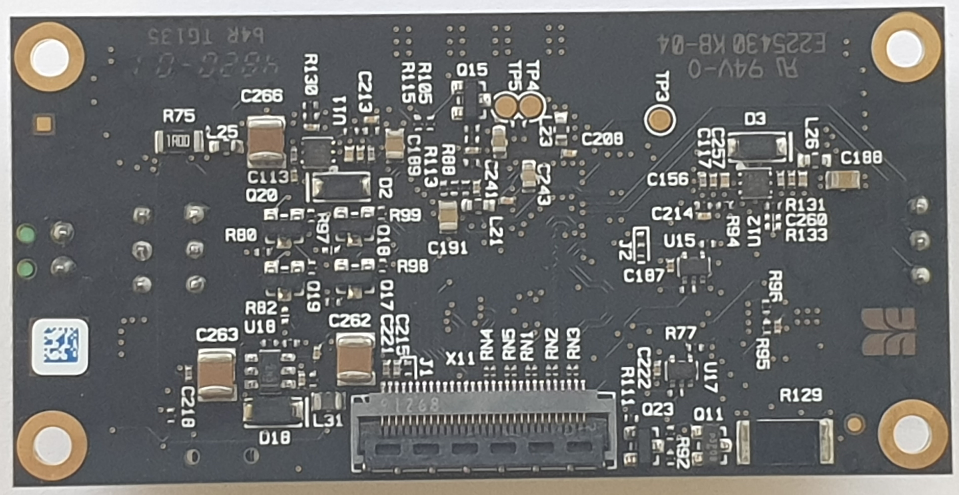
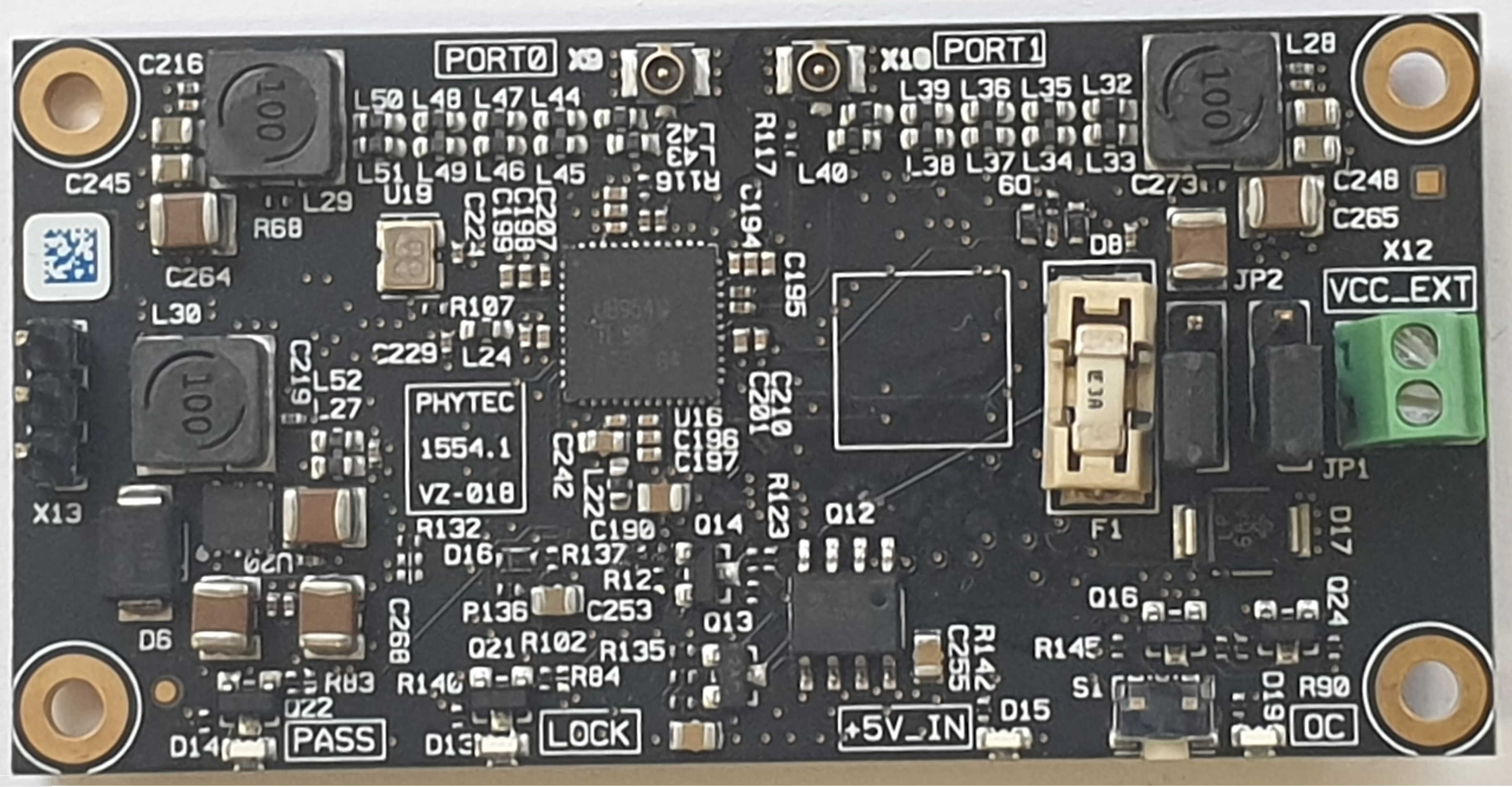
VZ-018 (PL1554.1) (Back/Front)
Specification
Function | VZ-018[1] |
Electrical Interface | |
Video Type | digital |
Video Input | 2 x phyCAM-L |
Data Format | FPD-LINK III (Power-Over-Coax) |
| Video Output | phyCAM-M |
| Data Format | MIPI CSI-2 |
Bridge Setting | I²C |
Supply Voltage | 4,5 V to 13,2 V |
Power Consumption (max) | 1700 mW + PPoC |
Power Consumption (type) | 1200 mW + PPoC |
Mechanical Daten | |
Dimensions(mm) | 68 x 34 |
Mounting | 4 x M2.5 |
Weight (PCB) | TBD |
Connections | |
phyCAM-L | TE 2337019 (UMCC Gen. 1) |
| phyCAM-M | FH41-30S-0.5SH |
| GPIO Extension | 1x3 2.54 Pin-Header |
VZ-018 Specification
| 1. | n/a: not applicable. All data may be subject to technical changes |
Interface Characteristics
| Symbol | min | type | max | Unit |
Operating Voltage phyCAM-M | VCAM | 4,75 | 5 | 5.25 | V |
Current Consumption | ICAM | - | 300 | 1500 | mA |
| FPD-LINK III voltages | VFPD | See datasheet DS90UB954 | V | ||
| FPD-LINK III Link Frequency | fFPD | - | 3,84 | - | GHz |
| I2C | see I2C specification for 3,3 V Fast-mode System | ||||
| I2C Clock Frequency | fI2C | - | 100 | 400 | kHz |
| Input high voltage (nRESET) | VIH_RST | 2,31 | 3,3 | 3,6 | V |
| Input low voltage (nRESET) | VIL_RST | - 0.5 | 0 | 0.4 | V |
Input high voltage (I2C_ADR) | VIH_ADR | 2,31 | 3,3 | 3,5 | V |
Input low voltage (I2C_ADR) | VIL_ADR | - | 0 | 0,99 | V |
| Input high voltage (CTRL2, CTRL4) | VIH | 2 | 3,3 | 5,5 | V |
Input low voltage (CTRL2, CTRL4) | VIL | - | 0 | 0,8 | V |
| Output high voltage (CTRL1, CTRL3) | VOH | Open-Drain (max. 5,5 Volt) | V | ||
| Output low voltage (CTRL1, CTRL3) | VOL | - | 0 | 0,4 | V |
| Output low voltage (CTRL1, CTRL3) | IOL | - | 10 | - | mA |
| Input high voltage (GPIO5, GPIO6) | VIH_GPIO | 2 | 3,3 | 3,5 | V |
| Input low voltage (GPIO5, GPIO6) | VIL_GPIO | -0,3 | 0 | 0,8 | V |
| Output high voltage (GPIO5, GPIO6) | VOH_GPIO | 2,4 | 3,3 | - | V |
| Output low voltage (GPIO5, GPIO6) | VOL_GPIO | - | 0 | 0,4 | V |
| Output low voltage (GPIO5, GPIO6) | IOL_GPIO | - | 4 | - | mA |
Operating temperature[2] | TOP | -25 | - | 70 | °C |
| Storage temperature | TSTG | -25 | - | 70 | °C |
| MIPI CSI-2 Bus length on the Module | LMIPI | - | - | 20 | mm |
| MIPI CSI-2 Intra-Pair Skew on the Module | Ldiff-Intra | - | - | 50 | µm |
| MIPI CSI-2 Inter-Pair Skew on the Module | Ldiff-Inter | - | - | 500 | µm |
| 2. | The junction temperature can be read out. Depending on the operating state, the ambient temperature may fluctuate. |
I2C Adresse Bridge (DS90UB954)
| Device | I²C-Address | Configuration CAM_ADR |
|---|---|---|
Bridge Sensor | 0x7A | LOW |
| 0x70 | HIGH |
VZ-018 I2C Addresses DS90UB954
The I²C addresses are specified hexadecimal in 8-bit representation. In Linux, it is possible to work with a 7-bit representation. In this case, the address value is to be shifted one digit to the right. The specification refers to the write address (bit 0 = 0). The read address is increased by 1 according to bit 1 = 1.
Additional I2C addresses can be configured within the camera sensor by software.
The address functionality must be enabled and assigned to a GPIO in the camera sensor before it can be used. For details, please refer to the sensor datasheet.
| Device | I²C-Address | Configuration J2 | Variant |
|---|---|---|---|
EEPROM | 0xAC | 1+2 | all |
| 0xAE | 2+3 |
VZ-018 (phyCAM-M) EEPROM I2C Addresses
The I²C addresses are specified hexadecimal in 8-bit representation. In Linux, it is possible to work with a 7-bit representation. In this case, the address value is to be shifted one digit to the right. The specification refers to the write address (bit 0 = 0). The read address is increased by 1 according to bit 1 = 1.
Jumper Map
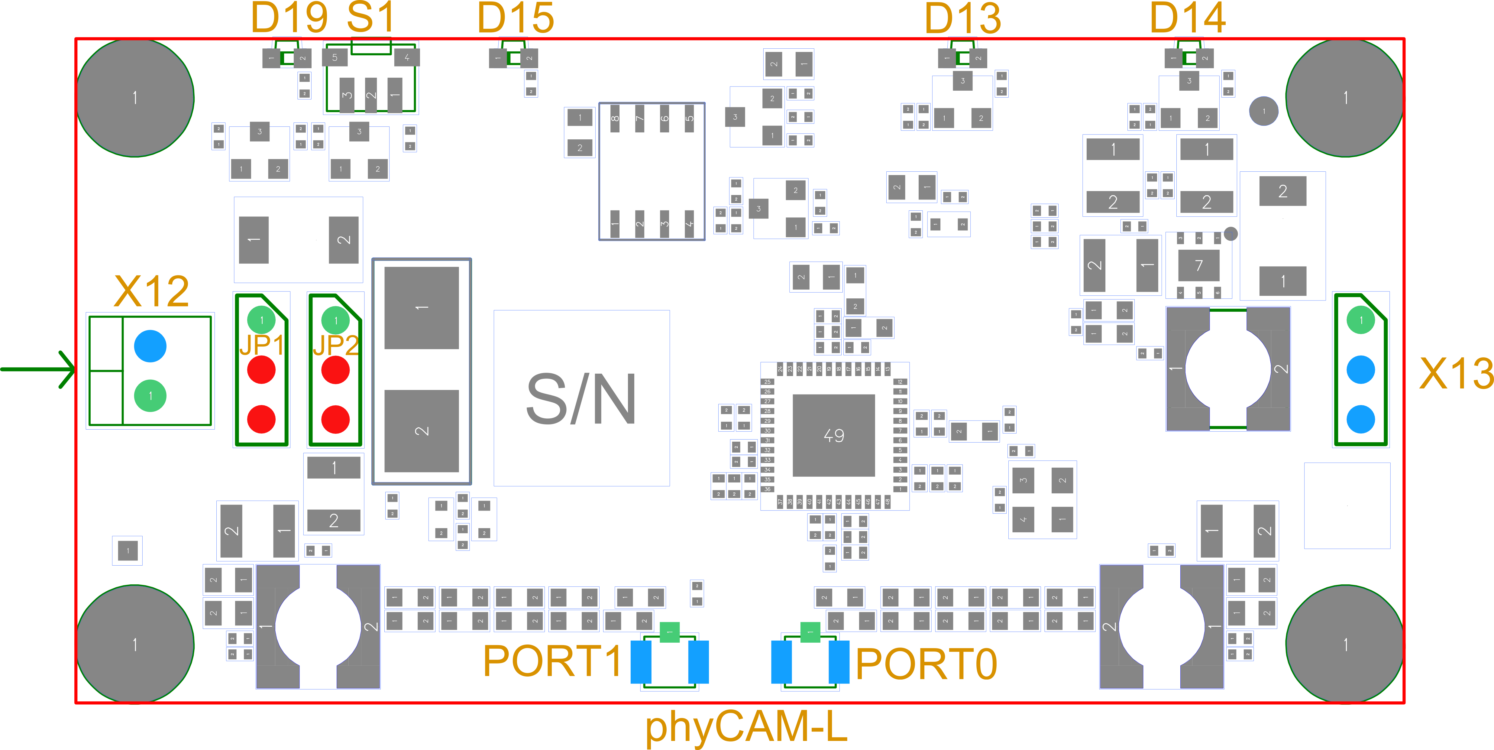
VZ-018 Jumper Plan (Front) (PL1554.1)
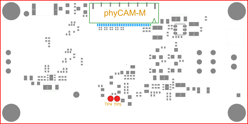
VZ-018 Jumper Plan (Back) (PL1554.1)
Dimensioned Drawing
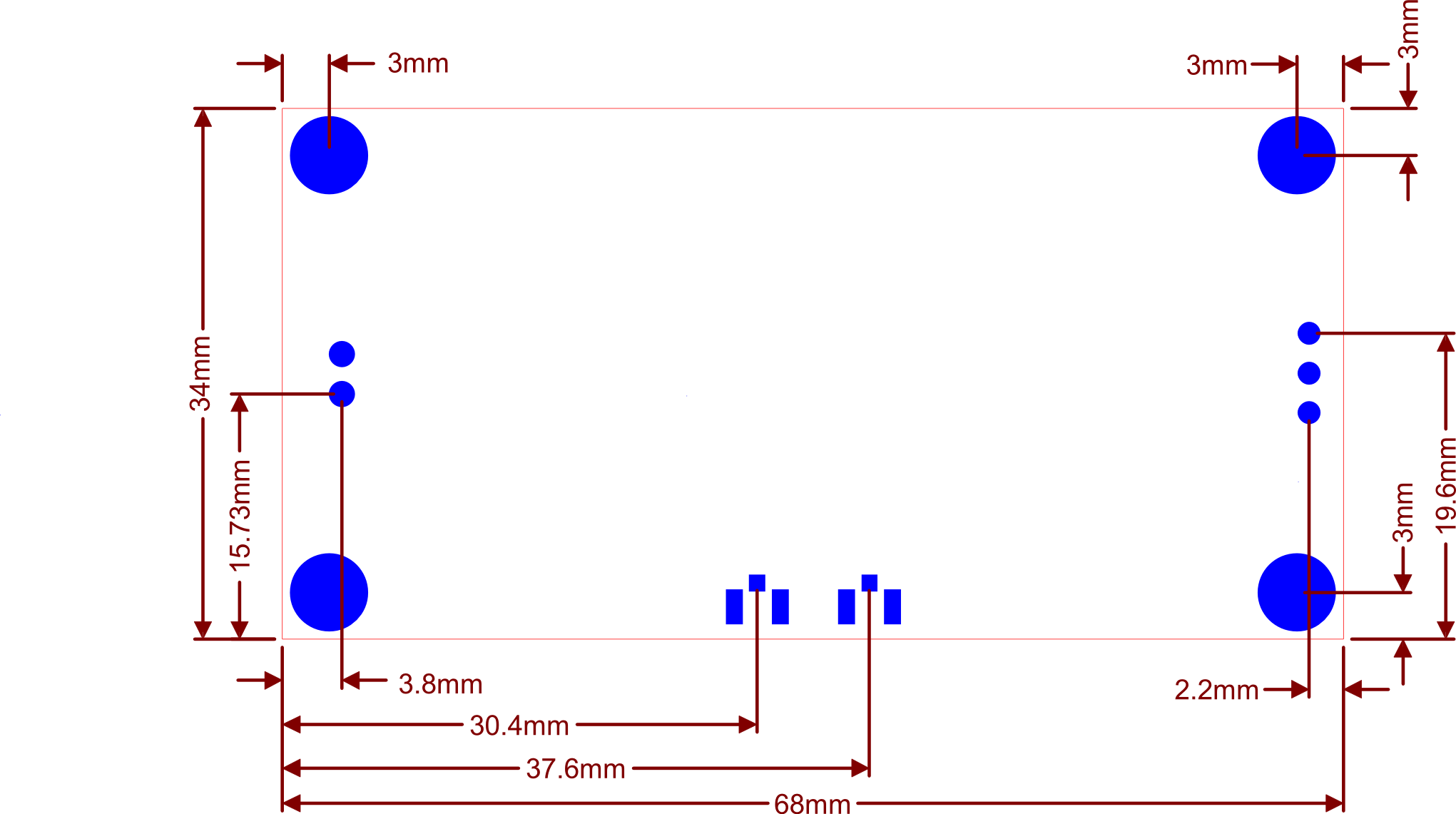
VZ-018 Dimensional Drawing Connector Positions (front) General Tolerance +- 0.25 mm

VZ-018 Dimensional Drawing Connector Positions (Back) General Tolerance +- 0.25 mm
Note
Current DXF and STEP data for your design are available on our website.
Revision History
Date | Version # | Changes in this manual |
01.03.2021 | L-1023e.A0 | New Release |
23.08.2021 | L-1023e.A1 | Updated information |