Total amount:
plus VAT.
OBSOLET - L-867Ae.A0 Quickstart Guide Start-Up phyCAM with Embedded Imaging Kit
Table of Contents
Copyrighted products are not explicitly indicated in this manual. The absence of the trademark (TM or ®) and copyright (©) symbols does not imply that a product is not protected. Additionally, registered patents and trademarks are similarly not expressly indicated in this manual.
The information in this document has been carefully checked and is considered to be entirely reliable. However, PHYTEC Messtechnik GmbH assumes no responsibility for any inaccuracies. PHYTEC Messtechnik GmbH neither gives any guarantee nor accepts any liability whatsoever for consequential damages resulting from the use of this manual or its associated product. PHYTEC Messtechnik GmbH reserves the right to alter the information contained herein without prior notification and accepts no responsibility for any damages that might result.
Additionally, PHYTEC Messtechnik GmbH offers no guarantee nor accepts any liability for damages arising from the improper usage or improper installation of the hardware or software. PHYTEC Messtechnik GmbH further reserves the right to alter the layout and/or design of the hardware without prior notification and accepts no liability for doing so.
@ Copyright 2021 PHYTEC Messtechnik GmbH, D-55129 Mainz.
Rights - including those of translation, reprint, broadcast, photomechanical or similar reproduction and storage or processing in computer systems, in whole or in part - are reserved. No reproduction may occur without the express written consent from PHYTEC Messtechnik GmbH.
| EUROPE | NORTH AMERICA | FRANCE | INDIA | CHINA |
Address: | PHYTEC Messtechnik GmbH | PHYTEC America LLC | PHYTEC France | PHYTEC Embedded Pvt. Ltd | PHYTEC Information Technology (Shenzhen) Co. Ltd. |
Ordering Information: | +49 6131 9221-32 | +1 800 278-9913 | +33 2 43 29 22 33 | +91-80-4086 7046/48 sales@phytec.in | +86-755-3395-5875 sales@phytec.cn |
Technical Support: | +49 6131 9221-31 | +1 206 780-9047 | +91-80-4086 7047 support@phytec.in | support@phytec.cn | |
Fax: | +49 6131 9221-33 | +1 206 780-9135 | +33 2 43 29 22 34 | +86-755-3395-5999 | |
Web Site: | http://phytec.in | http://www.phytec.cn |
Introduction
The SBC kits (Single-Board-Computer) from PHYTEC represent an ideal basis for testing and the first design steps with phyCAM camera modules. The kit forms the starting point for your development project. The kit can be used to develop and test application software before your own adapted hardware is available. It is also an optimal platform for testing special hardware extensions before you create a complex application board.
This optional step secures your design and at the same time provides software development with an opportunity to adapt newly added hardware components. Extensions can be easily connected via the extension interfaces of the baseboards included in the kit. In the simplest case, a freely wired hole grid structure is sufficient.
For certain combinations of controller modules, camera modules, and lenses, we offer ready-made kits. If the combination you require is not available, we recommend that you first put a similarly-equipped kit into operation and then connect the camera you require to the kit.
We will be happy to advise you on the best way to carry out your project.
SBC Kit Start-Up
Before you try out the camera and image processing functions, we recommend that you first familiarize yourself with the basic functions of the kit and the associated development environment. Each kit contains a Quick Start Guide that guides you through installing the software on your development PC and configuring the hardware.
Connecting and Starting the Camera
Note
Depending on the kernel version, the software installation may differ in some details from the described procedure.
When you purchase an SBC kit, you will receive the PHYTEC guarantee. If you encounter any difficulties during installation, PHYTEC support will help you!
Before You Start
The following components are required for the camera setup:
- PHYTEC SBC-Kit with power supply and serial connection (RS232 or USB)
- Camera module, with camera cable, lens holder, and lens
If you have ordered the corresponding kit as an Embedded Imaging Kit, all hardware components required for installation are already included.
As a rule, both the extension of an existing kit by one camera and the extension of an existing video kit by additional cameras is possible without problems with an existing phyCAM interface.
Before connecting and starting up the camera, carry out the first steps of the "Quick Start Instructions" of the respective kit. To start the scripts on the module, follow the steps to establish a serial connection with the module. You can use the terminal program suggested in the manual or your own terminal program.
To transfer saved image files to a PC (host) via Ethernet, follow the steps to establish an FTP connection. You can use the FTP server suggested in the manual or your own FTP server.
Connecting the Camera
Connecting a phyCAM-P Camera
Disconnect the system before connecting the camera.
Note
Be careful when connecting the cameras, otherwise, the brackets of the sockets may break.
Open the latch of the 33-pin FFC connector on the camera. Check which type of connector you have. The camera module can be equipped with a shift-lock type or a flip-lock type.
Shift-Lock connector:
- Pull the socket clip in the direction of the cable entry and lift it slightly.
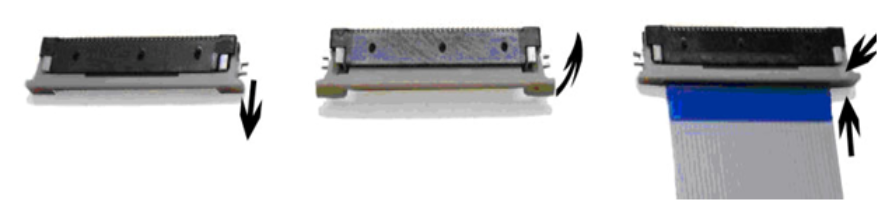
phyCAM-P Shift Lock – FFC Socket Camera Connection
- Plug the 33-pin FFC cable into the FFC socket with the contact surfaces facing downwards until you feel the stop. The reinforcement of the FFC cable (usually highlighted in color) points to the bracket of the socket.
- Lock the FFC socket by pressing the clip down again and pushing it in until it stops.
Flip-lock connectors:
- Lift the lock upwards.

phyCAM-P Flip Lock – FCC Socket Camera Connection
- Plug the 33-pin FFC cable into the FFC socket with the contact surfaces facing downwards until you feel the stop. The reinforcement of the FFC cable (usually highlighted in color) points to the bracket of the socket.
- Lock the FFC socket by carefully pressing down on the bracket.
A type-A FFC cable (stripped and reinforced on the same side) is supplied with the kit. This ensures the correct signal assignment between the camera and the baseboard in the kit.
The position of the camera socket on the baseboard can be found in the hardware manual of the kit. Parallel to the connector designation (e.g. X100), some basic boards also have "CAM" printed on the board. The phyCAM-P interface is a 33-pin FFC socket, which can be installed standing or lying on the board.
The FFC cable is plugged in exactly the same way as the cable is plugged into the camera FFC socket.

phyCAM-P FFC Socket Camera Connection
Connecting a phyCAM-S Camera
Disconnect the system before connecting the camera.
To connect the camera to a phyCAM-S system, a camera cable with an 8-pin Hirose connector is required (e.g. PHYTEC WK262 0.2). The Hirose plug is plugged into the matching counterpart on the camera module and the SBC. For orientation, there are two guide lugs on the upper side. These must snap into the corresponding recesses of the camera socket when plugged in.
phyCAM-S/S+ Hirose Camera Connection
The position of the camera jack on the SBC can be found in the kit's Quick Start manual. Parallel to the connector designation (e.g. X100), some basic boards also have the imprint "CAM" on the board. The phyCAM-S/S+ interface is a Hirose socket similar to the camera module, but more rarely an RJ-45 socket.
Warning
Boards with RJ-45 camera jacks usually also have an Ethernet RJ-45 jack. Make sure that the selected camera RJ-45 jack is not the Ethernet jack.
The RJ-45 connector of the camera cable is plugged into the RJ-45 camera jack on the motherboard.

phyCAM-S RJ-45 Camera Connection
The bracket on the plug serves both as reverse polarity protection and as a locking device. Push the RJ-45 plug into the socket until it audibly clicks into place.
Note
Be careful when connecting the cameras, otherwise, the brackets of the sockets may break.
Open the lock of the 30-pin FFC connector on the camera by lifting the lock upwards.

phyCAM-M Flip Lock – FCC Socket Camera Connection
- Plug the 33-pin FFC cable into the FFC socket with the contact surfaces facing downwards until you feel the stop. The reinforcement of the FFC cable (usually highlighted in color) points to the bracket of the socket.
- Lock the FFC socket by carefully pressing down on the bracket.
A type-A FFC cable (stripped and reinforced on the same side) is supplied with the kit. This ensures the correct signal assignment between the camera and the baseboard in the kit.
The position of the camera socket on the baseboard can be found in the hardware manual of the kit. Parallel to the connector designation (e.g. X100), some basic boards also have "CAM" printed on the board. The phyCAM-P interface is a 33-pin FFC socket, which can be installed standing or lying on the board.
The FFC cable is plugged in exactly the same way as the cable is plugged into the camera FFC socket.
Note
In the vertical version of the FFC socket, the contacts are also on the side opposite the bracket.
Demo Application
Bootloader Configuration
Before using the supplied examples, you should make sure that the camera module you are using is correctly configured in the bootloader environment.
Since BSP version PD16.0.1, the configuration for a camera module is done with the program "of_camera_selection", which is called up during the boot process in a script. The procedure is described in the corresponding Quickstart or "phyCAM - Getting Started" documentation of the Linux software.
Note
The PHYTEC Embedded Video Kits are pre-configured with the camera included in the kit.
For some controller models, extended documentation is available for configuring the cameras. Please check to see if your kit comes with "phyCAM - Getting Started" documentation in digital form.
General Procedure
Interrupt the boot processReset your SBC to restart the controller module.
During the output of:Hit m for menu or any other key to stop autoboot:
press ENTER to stop at the bootloader prompt.
Configure the Bootloader Environment
Enter the following call in your terminal program:edit env/config-expansions
Scroll down to the following line or lines using the 'Scroll down' button:
of_camera_selection -a 0x48 -p 0 -b phyCAM-P VM-010-BW
Program parameters:
-p: Port number of the camera interface [0/1]
-b: Bus type of the camera interface [phyCAM-P/phyCAM-S+]
-a: I²C address of the camera module [usually 0x48 at -p 0 / 0x5d at -p 1] see hardware manual of the respective camera module for more information
Camera module designations VM-0xx-BW / VM-0xx-COL (VM-009 for VM-009 and VM-050 for VM-050/051)
Press 'Ctrl+D' to temporarily save your changes and quit the editor.Save your changes:
saveenv
Reboot the Kernel:
Call:boot
to boot the kernel from the default boot source.
Start Live-Image
Warning
The scripts in the start directory are not optimized regarding frame rate, color conversion, resolution, etc. For optimal evaluation of the camera sensor, please use the camera-specific examples in the subdirectories.
Start the system and follow the boot process on the terminal of your serial connection.

Start-up Boot Screen
Log in to the system and use the >ls< command to list the existing files and subdirectories in your home directory.

Login and Home Directory File /Folder List
Change to the subdirectory with the GStreamer examples (cd xxx with "xxx" = name of the directory). List the contents of the directory again with >ls<.

GStreamer File/Folder List
The executable example scripts start with "bwcam" or "colcam". The file "func.sh" is a shell script in which general settings for the demo scripts are made. Files with the extension .txt contain extended register settings for the GStreamer plugin "i2c file". Details can be found in the document "LAN-052e_AppNote_Set_Cam_Register").
The demo scripts are structured as follows:
- Integration of the shell script (e.g.: `dirname $0`/func.sh)
- Use functions from the shell script (e.g. init_dev) to parameterize the GStreamer call.
- Configuring the camera with "v4l2-ctl
- Configuring the Videopipline with "media-ctrl".
- start the GStreamer (e.g.: gst-launch \)
- start various functions of the GStreamer (e.g.: v4l2src ! \)
To start a script, enter the desired file on the console, for example:
./colcam-fbdev_640x480.sh
Information about the free multimedia framework GStreamer and its functions can be found at www.gstreamer.net. General handling of the GStreamer is described in the respective BSP-Phytec-Quickstart.
Here is a selection of some demo scripts:
| Sample Script Name | Function | Notes |
|---|---|---|
| Displaying a Live Image | ||
| bwcam-fbdev_640x480.sh | The image data of a monochrome camera are continuously written into the frame buffer of the system and are visible on the display. | The display image is designed for a 640x480 dot display. For other display resolutions, the appropriate resolution must be set. |
| colcam-fbdev_640x480.sh | The image data of a color camera are continuously written into the frame buffer of the system and are visible on the display. | The display image is designed for a 640x480 dot display. For other display resolutions, the appropriate resolution must be set. |
| alle anderen fbdev Scripte | Write image data into the frame buffer of the system. | Examples with different resolutions and ROI functions. |
| Saving an Image (The saved file can be transferred to the host PC via the FTP connection) | ||
| bwcam-save_raw_full_res.sh | Saves the image data of a monochrome camera to the file "bw_image.raw". | The image data is written 1:1 to the file without overhead. |
| colcam-save_raw_full_res.sh | Saves the image data of a color camera to the file "col_image.raw". | The image data is written 1:1 to the file without overhead and without color conversion. |
| bwcam-save_jpg_full_res.sh | Converts the image data of a monochrome camera into a JPEG format and then writes the data into the file "bw_image.jpg". | The image data is saved in JPEG format. |
colcam-save_jpg_full_res.sh | Converts the image data of a color camera into a JPEG format and then writes the data into the file "col_image.jpg". | The image data is saved in JPEG format. |
| Network Transmission of Continuous Image Data | ||
| bwcam_xv.sh | Transmission of an uncompressed monochrome image data stream to a host. | Can only be used in conjunction with an Ethernet connection and an X server on the remote terminal. (Before the call, the output display must be initialized "export DISPLAY=<IP>:0"). |
| colcam_xv.sh | Transmission of an uncompressed color image data stream to an X server (host). | Can only be used in conjunction with an Ethernet connection and an X server on the remote terminal. (Before the call, the output display must be initialized "export DISPLAY=<IP>:0"). |
bwcam_mpeg4.sh Note Not available with all kit variants If the controller supports additional codecs, you can find more examples in the subdirectories of the cameras | Transmission of a compressed monochrome image data stream to an X server (host). | Can only be used in conjunction with an Ethernet connection and a suitable remote terminal (host with GStreamer). In order to be able to use this example, adaptations are necessary (e.g. IP address). Warning This example can only be run on certain controllers. The use of this example requires a deeper knowledge of Linux! |
colcam_mpeg4.sh Not available with all kit variants If the controller supports additional codecs, you can find more examples in the subdirectories of the cameras | Transmission of a compressed color image data stream to a host. | Can only be used in conjunction with an Ethernet connection and a suitable remote terminal (host with GStreamer). In order to be able to use this example, adaptations are necessary (e.g. IP address). Warning This example can only be run on certain controllers. The use of this example requires a deeper knowledge of Linux! |
| Sample Script Name | Function | Notes |
|---|---|---|
| Displaying a Live Image | ||
| bwcam-fbdev_640x480.sh | The image data of a monochrome camera are continuously written into the frame buffer of the system and are visible on the display. | The display image is designed for a 640x480 dot display. For other display resolutions, the appropriate resolution must be set. |
| colcam-fbdev_640x480.sh | The image data of a color camera are continuously written into the frame buffer of the system and are visible on the display. | The display image is designed for a 640x480 dot display. For other display resolutions, the appropriate resolution must be set. |
| all other fbdev scripts | Write image data into the frame buffer of the system. | Examples with different resolutions and ROI functions. |
| Saving an Image (The saved file can be transferred to the host PC via the FTP connection) | ||
| bwcam-save_raw_full_res.sh | Saves the image data of a monochrome camera to the file "bw_image.raw". | The image data is written 1:1 to the file without overhead. |
| colcam-save_raw_full_res.sh | Saves the image data of a color camera to the file "col_image.raw". | The image data is written 1:1 to the file without overhead and without color conversion. |
| bwcam-save_jpg_full_res.sh | Converts the image data of a monochrome camera into a JPEG format and then writes the data into the file "bw_image.jpg". | The image data is saved in JPEG format. |
colcam-save_jpg_full_res.sh | Converts the image data of a color camera into a JPEG format and then writes the data into the file "col_image.jpg". | The image data is saved in JPEG format. |
| Network Transmission of Continuous Image Data | ||
| bwcam_xv.sh | Transmission of an uncompressed monochrome image data stream to a host. | Can only be used in conjunction with an Ethernet connection and an X server on the remote terminal. (Before the call, the output display must be initialized "export DISPLAY=<IP>:0"). |
| colcam_xv.sh | Transmission of an uncompressed color image data stream to an X server (host). | Can only be used in conjunction with an Ethernet connection and an X server on the remote terminal. (Before the call, the output display must be initialized "export DISPLAY=<IP>:0"). |
bwcam_mpeg4.sh Note Not available with all kit variants If the controller supports additional codecs, you can find more examples in the subdirectories of the cameras | Transmission of a compressed monochrome image data stream to an X server (host). | Can only be used in conjunction with an Ethernet connection and a suitable remote terminal (host with GStreamer). In order to be able to use this example, adaptations are necessary (e.g. IP address). Warning This example can only be run on certain controllers. The use of this example requires a deeper knowledge of Linux! |
colcam_mpeg4.sh Not available with all kit variants If the controller supports additional codecs, you can find more examples in the subdirectories of the cameras | Transmission of a compressed color image data stream to a host. | Can only be used in conjunction with an Ethernet connection and a suitable remote terminal (host with GStreamer). In order to be able to use this example, adaptations are necessary (e.g. IP address). Warning This example can only be run on certain controllers. The use of this example requires a deeper knowledge of Linux! |
Example Script Information
Note
The scripts are continuously updated and adapted by PHYTEC. Depending on the kernel version, controller module, and camera module, the above examples may differ.
Scripts created specifically for a camera/camera sensor are located in separate subdirectories identified by the camera sensor name or description. Note that some scripts also depend on the hardware platform, meaning they are only for phyCARD or only for phyCORE platform.
Troubleshooting
In this section, we provide tips for step-by-step troubleshooting if an initial operation is not immediately successful.
Display Test
On the console, type the following command:
fbtest
Various geometric shapes and color patterns appear on the display.
Possible error: No image is shown on the display:
Remedy:
- Check the connection to the display/monitor.
- Check the backlight connection.
Camera Live Image Test
Call up a file via the console, with a color variant matching your camera (monochrome/color) and the resolution matching your display.
Example:
./colcam-fbdev_640x480.sh

Example Script for the Camera Live Image Test
Depending on the BSP version, the script file automatically tries to load the correct driver or checks whether the preset driver could be loaded. If a corresponding camera is found, a message is displayed:
camera 0-0: Detected an MT9V022 chip ID 1313, color sensor
and the live image is displayed on the screen.
Possible Error: No camera is detected.

No Camera Error
Remedy:
- Check the connection to the camera.
- Linux: check if the camera is supported by the kernel.
- Linux: check the timeliness of GStreamer examples
Possible Error: live image is displayed; delayed and with a slow frame rate
Remedy:
Due to several factors, a live image display with the highest frame rate is not always possible. The following factors can play a role here:
- Image data quantities (e.g.: image resolution, color format, etc.).
- Intermediate algorithms can require a lot of computing power.
- Conversion of color formats (e.g. Bayer Pattern to RGB) requires computing power.
- Different computing power and multimedia support of the controllers. It is possible that not all multimedia accelerators are supported by the demo application.
- Linux: As a modular framework, GStreamer is not speed-optimized.
In this case, the amount of image data and the algorithms used should be adapted to the task.
Changing Camera Modules Register Settings
The camera sensors offer various possibilities to influence image acquisition.
The corresponding settings are made in the camera registers. These registers can be read and written via the I²C interface. Many settings are already set automatically by the camera driver according to the driver calls.
Some of the more specific settings cannot be changed using the driver functions. The application programmer can access the camera registers directly and adjust the values accordingly.
Embedded Linux
PHYTEC's digital camera modules are supported by the appropriate camera drivers found in the PHYTEC Linux-BSP of the embedded controller module. The list of supported camera modules is constantly being broadened. The camera modules included in the respective distribution (kernel version) can be queried in the Sys directory of the file system. The driver directory depends on the version, for example under :
/sys/bus/i2c/drivers
The name of the camera driver usually refers to the sensor chip used.
Camera Name | Driver Designation |
VM-006-Serie (ON Semiconductor MT9M001-Sensor) | mt9m001 |
VM-008-Serie (Renesas TW9910 Video Decoder) | tw9910 |
VM-009-Serie (ON Semiconductor MT9M131-Sensor) | mt9m111 |
VM-010-Serie (ON Semiconductor MT9V024-Sensor) | mt9v032 |
VM-011-Serie (ON Semiconductor MT9P031/006-Sensor) | mt9p031 |
VM-012-Serie (ON Semiconductor VITA1300-Sensor) | phytec-vm012 |
VM-016-Serie (ON Semiconductor AR0144-Sensor) | ar0144 |
VM-05x-Serie (Heimann Sensor HTPAd-Sensor) | phytec-vm050 |
Examples for phyCAM Camera Modules and Driver Names
The type designations of other camera sensors can be found in the respective hardware manuals of the camera module.
The driver is accessed via the Video4Linux 2 interface (V4L2) of the camera driver from a separate application. Free multimedia frameworks such as the GStreamer can also access the driver via the V4L2 interface.
V4L2 functions which are supported by the drivers can be determined by Capability Querying. This mechanism and the description of the functions themselves are explained in the general descriptions for V4L2 (see Video for Linux Two API Specification).
In order to quickly test camera functions and display a camera image, it is advantageous to work with a simple tool.
For this purpose, PHYTEC provides scripts for the GStreamer, which is widely used in the Linux world. The GStreamer can be configured without programming effort by simple script calls. The scripts supplied by PHYTEC use the GStreamer to display and transfer image data streams. Furthermore, single images or image sequences can be saved in different formats.
These scripts also show how the GStreamer examples can be extended to include access to the camera registers. The desired configuration can be set by the user in an editable text file by selecting and deselecting the register accesses. An extension of the file by the user is also possible.
This procedure is explained in a separate document:
LAN-052-d_AppNote_Set_Cam_Register
Depending on the BSP version, there are many other programs and programming examples, for example:
- ...\v4l2_c-examples\...
(Access to the v4l2 interface from own C - programs) - ...\opencv_examples\...
(Access to the v4l2 interface from OpenCV) - ...\gstreamer_examples\tools\...
(Access to the registers of the camera modules via the I²C bus)
Basic Principles
General Access to the Camera Registers
Warning
The values of some registers are important for the correct function of the camera and the interference-free image acquisition.
Changing these register values can lead to incorrect image display or instability of the system. For this reason, direct control of the registers under Linux is only possible in debug mode. Before changing values, thoroughly check to what extent this can affect the function of the camera or the stability of the system.
Some registers are managed by the respective camera driver. This means that changing certain register contents can affect the driver process or the driver can reset certain contents.
General Access under Linux
To access the camera registers, the V4L2 API VIDIOC_DBG_G_REGISTER and VIDIOC_DBG_S_REGISTER are available.
Warning
The functions can only be used if the corresponding driver has been compiled in debug mode (CONFIG_VIDEO_ADV_DEBUG).
In the PHYTEC distribution, the supplied camera drivers have already been created in debug mode.
The register functions can be integrated by the user into his own application. Prior to such an integration, it is advantageous to test the effect of certain register settings and make them visible with simple tools.
Setting the Camera Registers Using a Configuration File
During initial operation or when adapting the camera properties to an application, it is not only advantageous to set individual camera registers, but several camera registers in one step.
For this purpose, PHYTEC provides a configuration file and the corresponding tools to use this file. This file can be edited and adapted by the user himself.
Structure of the Configuration File
PHYTEC provides a sample configuration file as a TXT file for the corresponding camera. The name is freely selectable. The structure of the file is predefined.
For easy differentiation, PHYTEC has integrated the name of the sensor into the file name.
Examples:
- „register-settings-mt9v022.txt“ (for VM-007)
- „register-settings-mt9m001.txt“ (for VM-006)
- „register-settings-mt9m131.txt“ (for VM-009)
The structure of a register access is as follows.
chip-address, register-address, value, [mode]
chip-address = I²C base address of the camera sensor,
Format: hexadecimal 8-bit (mt9v022 = 0x48 / mt9m001 = 0x5d)
register-address = Address of the register to be changed in the camera.
Format: hexadecimal 8-bit
value = value to be written into the register
Format: optionally hexadecimal 16-bit (0x...) or decimal
mode = Enables logical linking of the current register content with the specified value (optional).
Possible parameters:
a (and, logical AND operation)
o (or, logical OR operation)
x (xor, logical exclusive OR operation)
The # character introduces a comment. This means that the selection or deselection can be done with a "#" in front of the line.
Many different options are already included in the camera sensor examples prefabricated by PHYTEC.
In the following, the gain value (electrical signal amplification) of the MT9V022 will be set to the factor x2. The # sign in the corresponding lines has been removed for this purpose.
---------------------------
#  set MT9V022 AGC
#  ===============
#  set AGC automatic
#0x48,0xAF,0x0002,o	# automatic = on

#  set AGC manual
0x48,0xAF,0xFFFD,a	# automatic = off
#0x48,0x35,0x0010	# set gain = 1.00
#0x48,0x35,0x0014	# set gain = 1.25
#0x48,0x35,0x0018	# set gain = 1.50
#0x48,0x35,0x001C	# set gain = 1.75
0x48,0x35,0x0020	# set gain = 2.00
#0x48,0x35,0x0024	# set gain = 2.25
#0x48,0x35,0x0028	# set gain = 2.50
#0x48,0x35,0x002C	# set gain = 2.75
#0x48,0x35,0x0030	# set gain = 3.00
…
---------------------------
After using the modified script file, the image is generated with a fixed gain value (Gain = 2,00). Further settings such as switching off the AEC and the automatic BLC can be found in the example settings supplied by PHYTEC.
Further descriptions of the register assignments of the camera sensors can be found on the homepage of the corresponding camera sensor manufacturer (mt9m001, mt9v022 see www.onsemi.com).
The sample configuration file for the various camera sensors can be found for:
- Linux directly in the directory where the example scripts for the GStreamer are stored:
…/gstreamer_examples/…
Note
If several write operations are specified on the same register, they are executed in exactly this order. This usually means that the last written value is in the register.
Make sure that you do not activate more than one option.
When using the logical operators (AND, OR, XOR), the use of multiple write operations can be useful to modify certain parts of a register.
Example:
Write the value 0x35 into the lower byte of the register without changing the upper byte.
chip-address, register-address, 0xFF00,a # unteres Byte löschen
chip-address, register-address, 0x0035,o # Wert 0x35 dort
einschreiben
Using the Configuration File under Linux
Access via GStreamer
The scripts supplied by PHYTEC show how the GStreamer examples can be modified to include access to the camera registers. The desired configuration can be set by the user in the editable text file by selecting and deselecting the register accesses. Users can also modify the file.
Prerequisites
GStreamer - Plug-in for direct register access (part of the PHYTEC distribution).
Integrating the Configuration File under Linux
The PHYTEC script with the GStreamer example for taking a single jpeg image from the VM-012-BW camera module (VITA1300) in black/white is selected as the starting point ("vita1300_bw_save_jpg_full_res.sh").
Contents (abbreviated)
---------------------------
echo "start gstreamer"
echo "==============="

gst-launch-1.0 \
	v4l2src num-buffers=$NUMBER_OF_PIC device=$IPU1_CSI0_DEVICE ! \
	i2c file=`dirname $0`/../register-settings-vita1300.txt show=0 dev=$CAM_DEVICE ! \
	video/x-raw,format=GRAY8,depth=8,width=1280,height=1024 ! \
	vita1300_remapper mode=0 passthrough=false ! \
	videoconvert ! \
	jpegenc ! \
	multifilesink location=bw_$CAMERA.jpg
---------------------------
This example takes a picture "bw_VM-012(vita1300).jpg" in jpeg format. The camera sensor VITA1300 works in default mode with automatic settings AGC/AEC and automatic BLC.
In order to be able to set certain registers, the plug-in, which can process the desired I²C registers from a file, must also be listed.
The plugin "i2c file=[name of the text file] show=0 dev=$CAM_DEVICE! \" is placed between the initialization and the image request.
---------------------------
	…
V4L2src num-buffers=1 ! \
	i2c file=`dirname $0`/../register-settings-vita1300.txt show=0 	dev=$CAM_DEVICE ! \
	video/x-raw-gray$FRAME_SIZE ! \
	…
---------------------------
The specified text file ( "register-settings-vita1300.txt") is located in the gstreamer root directory. The setting "show=1 causes an additional output of the register accesses on the serial interface.
Further parameters of the "i2c"-Plugin are listed by entering the command "gst-inspect i2c".
Note
In systems with multiple cameras, the same text file can be used for cameras with different I2C addresses using the parameter addr=[hex address of the device on the I2C bus]. The I2C device address in the text file is overwritten by the "addr parameter".
Example for video-device_0 at address 0x48 and video-device_1 at address 0x4c:
i2c addr=0x48 file=register-settings-vita1300.txt show=0 dev=/dev/video0 ! \
i2c addr=0x4c file=register-settings-vita1300.txt show=0 dev=/dev/video1 ! \
Revision History
Date | Version # | Changes in this Manual |
01.03.2021 | Manual L-867Ae.A0 | New Release |