Total amount:
plus VAT.
Getting Started Guide - phyCAM with phyBOARD-Pollux i.MX 8M Plus (L-1029e.A1)
Table of Contents
Introduction
The SBC (Single Board Computer) kits from PHYTEC represent an ideal basis for testing and the first design steps with phyCAM camera modules. The kit forms the starting point for your development project. The kit can be used to develop and test application software before your own adapted hardware is available. It is also an optimal platform for testing special hardware extensions before you create a complex application board.
This optional step secures your design while at the same time providing software developers with an opportunity to adapt newly added hardware components. Extensions can be easily connected via the extension interfaces of the baseboards included in the kit. In the simplest case, a freely wired hole grid structure is sufficient.
For certain combinations of controller modules, camera modules, and lenses, we offer ready-made kits. If the combination you require is unavailable, we recommend that you first put a similarly equipped kit into operation and then connect the camera you require to the kit.
We will be happy to advise you on the best way to carry out your project.
SBC Kit Start-Up
Before you try out the camera and image processing functions, we recommend that you first familiarize yourself with the basic functions of the kit and the associated development environment. Each kit contains a Quick Start Guide that guides you through installing the software on your development PC and configuring the hardware.
Before You Start
The following components are required for the camera setup:
- PHYTEC SBC-Kit with power supply and serial connection (RS232 or USB)
- Camera module with camera cable, lens holder, and lens
- Network cable
- HDMI monitor with an HDMI cable (not included in the kit)
If you have ordered the corresponding kit as an Embedded Imaging Kit, all hardware components required for installation are already included.
As a rule, both the extension of an existing kit by one camera and the extension of an existing video kit by additional cameras is possible without problems with an existing phyCAM interface.
Before connecting and starting up the camera, carry out the first steps of the "Quick Start Instructions" of the respective kit. To start the scripts on the module, follow the steps to establish a serial connection with the module. You can use the terminal program suggested in the manual or your own terminal program.
To transfer saved image files to a PC (host) via Ethernet, follow the steps to establish an FTP connection. You can use the FTP server suggested in the manual or your own FTP server.
Connecting and Starting the Camera
Note
Depending on the kernel version, the software installation may differ in some details from the described procedure.
When you purchase an SBC kit, you will receive the PHYTEC guarantee. If you encounter any difficulties during installation, PHYTEC support will help you!
Overview
The i.MX 8M Plus Microcontroller supports two MIPI CSI-2 camera interfaces:
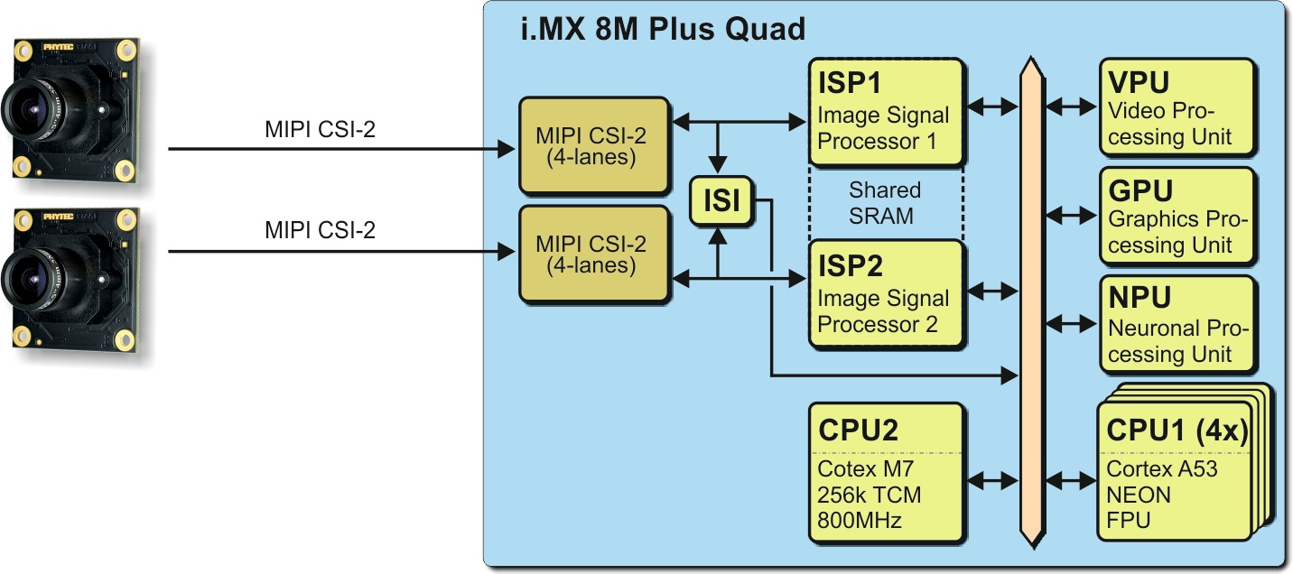
Camera Interfaces of i.MX 8M Plus Controller (Quad) Block Diagram
On the phyCORE-i.MX 8M Plus, the CSI1/CAM1 and CSI2/CM2 camera paths go out as CSI-2 MIPI signal:
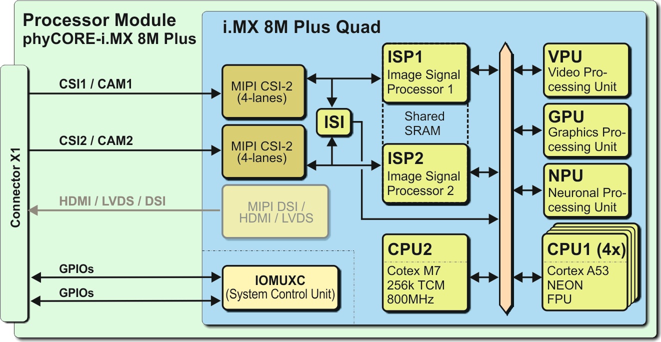
CAM_1 (CSI1) and CAM_2 (CSI2) Present on Connector X1
On PHYTEC or customer carrier boards, the interfaces are led out as phyCAM-M. For more information on phyCAM-M, see the phyCAM-Manuals on our website.
On the phyBOARD-Pollux baseboard, the camera interfaces are led out as phyCAM-M (MIPI CSI-2) interfaces. Here you can connect different phyCAM-M camera modules:

phyCAM-M Camera Interfaces of phyCORE-i.MX 8M Plus (Quad) and the output on the phyBOARD-Pollux-i.MX 8M Plus
The BSP shipped with the Kit includes the software drivers for the supported phyCAM-M camera modules. The drivers are compatible with v4l2. GStreamer scripts are also included for the evaluation of the camera modules. If you need the camera interface to connect to your own camera module, an adapter to phyCAM-M is necessary.
Camera Connectors on the Pollux - Carrier Boards
The development kits for the i.MX 8M Plus phyBOARD-Pollux contains:
- one carrier board (phyBOARD-Pollux)
- one phyCORE-i.MX 8M Plus module SOM (phyCORE-i.MX 8M Plus)
The phyCORE-i.MX 8M Plus is plugged into the carrier board.
On the phyBOARD-Pollux baseboard (PBA-C-17), we convert the MIPI CSI-2 interfaces into a phyCAM-M standard.
- phyCAM-M camera interface 1 (support on connector X11)
- phyCAM-M camera interface 2 (support on connector X12)
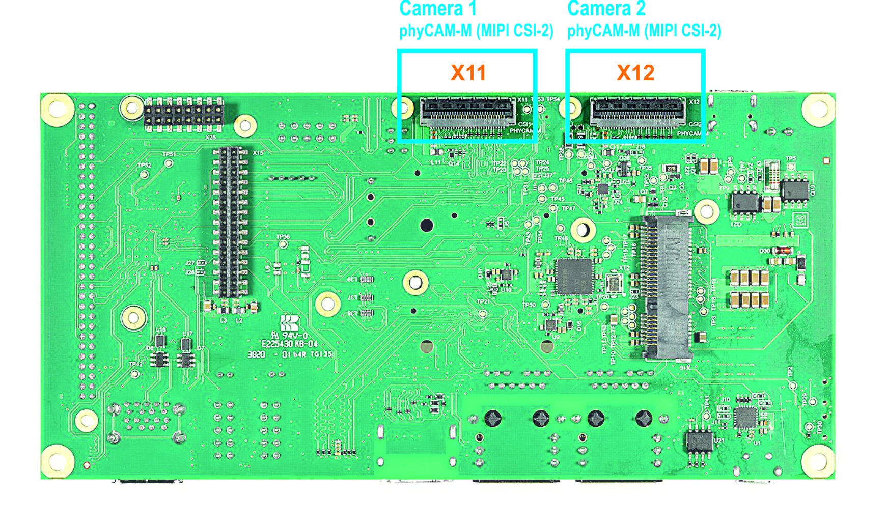
Camera Interface on phyBOARD-Pollux up PCB Version PL1552.0
Note
If you use the phyCAM-M interface, use an FFC cable that is especially suitable for FH41 connectors (e.g. PHYTEC WF271). Standard FFC cables can cause a short circuit.
Connecting the phyCAM-M Camera
A type-A FFC cable (stripped and reinforced on the same side) is supplied with the kit. This ensures the correct signal assignment between the camera and the baseboard in the kit.
The position of the camera socket on the baseboard can be found in the hardware manual of the kit. Parallel to the connector designation (e.g. X100), some basic boards also have "CAM" printed on the board. The phyCAM-M interface is a 30-pin FFC socket, which can be installed standing or lying on the board.
The FFC cable is plugged in exactly the same way as the cable is plugged into the camera FFC socket.
Note
In the vertical version of the FFC socket, the contacts are also on the side opposite the bracket.
Open the lock of the 30-pin FFC connector on the camera by lifting the lock upwards.

phyCAM-M Flip Lock – FCC Socket Camera Connection
- Plug the 30-pin FFC cable into the FFC socket with the contact surfaces facing downwards until you feel the stop. The reinforcement of the FFC cable (usually highlighted in color) points to the bracket of the socket.
- Lock the FFC socket by carefully pressing it down on the bracket.
Supported Camera Boards (YOCTO Linux PD21.1.1 and higher)
The cameras and the camera interface are supported as sub-devices. To configure the v4l2 framework is the handler "media-ctl" used, see Configure Camera and Controller Camera Interface with "media-ctl"
Tip
The device tree of the camera VM-016 (sensor AR0144) at csi_port_1 is pre-selected in PD21.1.1 To use other the VM-016 at other port or dual or other cameras (e.g. VM-017/117) the device tree must be changed. See Change the Camera Types in Standard Vision Image
Supported Camera Types in Standard Vision Image (phytec-vision-image-phyboard-pollux-imx8mp-2)
Per default the following Camera types are supported in the image:
- VM-016-BW-M series (VM-016-BW-M, VM-016-BW-M-M12, VM-016-BW-M-H, …) based on camera sensor “AR0144”
- VM-016-COL-M series (VM-016-COL-M, VM-016-COL-M-M12, VM-016-COL-M-H, …) based on camera sensor “AR0144”
After login, you can start working with the Demo Scripts.
Hardware Configuration | Possible Parameters | Default I²C-address | ||||
phyCAM Camera Model (part number) | Connected to | csi_port | cam_bus_type | cam_i2c_address | ||
VM-016-__-M (-M12/-H) | X11 on Pollux board | 1 | phyCAM-M | 0x10, 0x18 | 0x10 | |
Note
I²C addresses of the camera are set by hardware configuration (jumper setting on the camera and/or on the baseboard. Please refer to the L-1018e.A0 phyCAM-M VM-016 1/4“ 1,0 MPixel Global Shutter Camera Module Guide and the L-1009e.A0 phyCORE-i.MX 8M Plus / phyBOARD-Pollux (1549.0 / 1552.0) Hardware Manual.
Change the Camera Types or Connected Port in Standard Vision Image (phytec-vision-image-phyboard-pollux-imx8mp-2)
The following camera types are interchangeable in the image:
- VM-016-BW-M series (VM-016-BW-M, VM-016-BW-M-M12, VM-016-BW-M-H, …) based on camera sensor “AR0144”
- VM-016-COL-M series (VM-016-COL-M, VM-016-COL-M-M12, VM-016-COL-M-H, …) based on camera sensor “AR0144"
- VM-116-BW-M series (VM-116-BW-M, VM-116-BW-M-M12, …) based on camera sensor “AR0144”
- VM-116-COL-M series (VM-116-COL-M, VM-116-COL-M-M12, …) based on camera sensor “AR0144”
- VM-016-BW-L series (VM-016-BW-L, VM-016-BW-L-M12, VM-016-BW-L-H, …) based on camera sensor “AR0144”
- VM-016-COL-L series (VM-016-COL-L, VM-016-COL-L-M12, VM-016-COL-L-H, …) based on camera sensor “AR0144”
- VM-017-BW-M series (VM-017-BW-M, VM-017-BW-M-M12, VM-017-BW-M-H, …) based on camera sensor “AR052x” (adapted device tree and driver necessary)
- VM-017-COL-M series (VM-017-COL-M, VM-017-COL-M-M12, VM-017-COL-M-H, …) based on camera sensor “AR052x” (adapted device tree and driver necessary)
- VM-117-BW-M series (VM-117-BW-M, VM-117-BW-M-M12, …) based on camera sensor “AR052x” (adapted device tree and driver necessary)
- VM-117-COL-M series (VM-117-COL-M, VM-117-COL-M-M12, …) based on camera sensor “AR052x” (adapted device tree and driver necessary)
- VM-017-BW-L series (VM-017-BW-L, VM-017-BW-L-M12, VM-017-BW-L-H, …) based on camera sensor “AR052x” (note: in progress)
- VM-017-COL-L series (VM-017-COL-L, VM-017-COL-L-M12, VM-017-COL-L-H, …) based on camera sensor “AR052x” (note: in progress)
To register the cameras you need an adapted device tree.
How to Change the Device Tree
- During the boot sequence, press a key (use a terminal program e.g. "Putty") to arrive the bootloader
- u-boot=> edit fdt_file
- Edit: <type here your device tree> (e.g. "imx8mp-phyboard-pollux-rdk-vm016-csi2.dtb")
PHYTEC supports same device trees, see the right device tree in following list:
Hardware Configuration | Possible Parameters | Default I²C-address | Device Tree | |||
phyCAM Camera Model | Connected to | csi_port | cam_bus_type | cam_i2c_address | name of the device tree | |
VM-_16-__-M (-M12/-H) | X11 on Pollux | 1 | phyCAM-M | 0x10, 0x18 | 0x10 | imx8mp-phyboard-pollux-rdk-vm016.dtb |
| VM-016-__-L (-M12/-H) | X11 on Pollux via VZ-018 | 1 | phyCAM-L | 0x10, 0x18 | 0x10 | imx8mp-phyboard-pollux-rdk-vm016.dtb (driver must be loaded via modprobe) |
VM-_16-__-M (-M12/-H) | X12 on Pollux | 2 | phyCAM-M | 0x10, 0x18 | 0x10 | imx8mp-phyboard-pollux-rdk-vm016-csi2.dtb |
| VM-016-__-L (-M12/-H) | X12 on Pollux via VZ-018 | 2 | phyCAM-L | 0x10, 0x18 | 0x10 | imx8mp-phyboard-pollux-rdk-vm016-csi2.dtb (driver must be loaded via modprobe) |
VM-_16-__-M (-M12/-H) and VM-_16-__-M (-M12/-H) | X11 Pollux X12 Pollux | 1 2 | phyCAM-M phyCAM-M | 0x10, 0x18 0x10, 0x18 | 0x10 0x10 | imx8mp-phyboard-pollux-rdk-dual-vm016.dtb |
VM-016-__-L (-M12/-H) and VM-016-__-L (-M12/-H) | X11 Pollux X12 Pollux | 1 2 | phyCAM-L phyCAM-L | 0x10, 0x18 0x10, 0x18 | 0x10 0x10 | imx8mp-phyboard-pollux-rdk-dual-vm016.dtb (driver must be loaded via modprobe) |
VM-_17-__-M (-M12/-H) | X11 on Pollux | 1 | phyCAM-M | 0x36, 0x37 | 0x36 | imx8mp-phyboard-pollux-rdk-vm017.dtb |
VM-017-__-L (-M12/-H) | X11 on Pollux via VZ-018 | 1 | phyCAM-L | 0x36, 0x37 | 0x36 | imx8mp-phyboard-pollux-rdk-vm017.dtb (driver must be loaded via modprobe) |
VM-_17-__-M (-M12/-H)* | X12 on Pollux | 2 | phyCAM-M | 0x36, 0x37 | 0x36 | imx8mp-phyboard-pollux-rdk-vm017-csi2.dtb |
VM-017-__-L (-M12/-H)* | X12 on Pollux via VZ-018 | 2 | phyCAM-L | 0x36, 0x37 | 0x36 | imx8mp-phyboard-pollux-rdk-vm017-csi2.dtb (driver must be loaded via modprobe) |
VM-_17-__-M (-M12/-H) and VM-_17-__-M (-M12/-H) | X11 Pollux X12 Pollux | 1 2 | phyCAM-M phyCAM-M | 0x36, 0x37 0x36, 0x37 | 0x36 0x36 | imx8mp-phyboard-pollux-rdk-dual-vm017.dtb |
VM-017-__-L (-M12/-H) and VM-017-__-L (-M12/-H) | X11 Pollux X12 Pollux | 1 2 | phyCAM-L phyCAM-L | 0x36, 0x37 0x36, 0x37 | 0x36 0x36 | imx8mp-phyboard-pollux-rdk-dual-vm017.dtb (driver must be loaded via modprobe) |
Note
* When both camera interfaces are used simultaneously, each supports maximum resolution up to 1080p (1936x1188). E.g. two VM-017 camera boards can only be used up to maximum resolution up to 1080p (1936x1188). Also, the CAM2 (X12) interface supports a maximum resolution of up to 1080p (1936x1188).
Note
I²C addresses of the camera are set by hardware configuration (jumper setting on the camera and/or on the baseboard. Please refer to the VM-x17-_ manuals (L-1020e.A0 phyCAM-L VM-017 1/2.5“ 5,1 MPixel Camera Module Guide/L-1021e.A0 phyCAM-M VM-017 1/2.5“ 5,1 MPixel Camera Module Guide/L-1022e.A0 phyCAM-M VM-117 1/2.5“ 5,1 MPixel MINI Camera Module Guide and the L-1009e.A0 phyCORE-i.MX 8M Plus / phyBOARD-Pollux (1549.0 / 1552.0) Hardware Manual.
How to activate the VM-017/VM-117 camera series
Please follow the instructions of “README.md” from PHYTEC FTP Server: https://download.phytec.de/ImageProcessing/phyBOARD-Pollux-i.MX8MP_linux_PD21.1.1/VM-017/
After reboot and login, the AR052x camera driver present. Now the VM-0x17 driver (AR052x) is ready for use and you can start working with the Demo Scripts.
Demo Scripts
If you want to see the live images, we recommend using a HDMI monitor on the Pollux Board.
There are 3 subdirectories with demo scripts for the cameras:
- GStreamer-examples
- v4l2_c-examples
- opencv-examples
Note
Remove the qt-demo at first startup with the \gstreamer-examples\remove_qt_demo.sh script. Otherwise, the qt-demo is always present on the display.
GStreamer Scripts
After login, change into the directory: \gstreamer-examples\..
cd gstreamer_examples <ENTER>.
Now you can start working with the GStreamer demo scripts.
Start the scripts with the word phrase "col" or "bw" depending on the connected camera color type.
- _cam-fbdev_1280x720.sh: scripts show a live stream on display
- _cam-save_jpg_full_res.sh: scripts save a JPG File in this directory
- _cam-save_raw_full_res.sh: scripts save a RAW File in this directory
- sh: scripts detect the camera type and define the parameter for the scripts
- sh: scripts remove the qt-demo from autostart
- sh: scripts turn on/off if Wayland necessary or not
Subdirectories:
- more_ar0144_scripts: contain more scripts for the VM-016 camera series (v4l-ctrl_ar0144.txt list the v4l2-controls for this camera)
- more_ar052x_scripts: contain more scripts for the VM-017/117 camera series (v4l-ctrl_ar052x.txt list the v4l2-controls for this camera)
- vpu_enc_dec_scripts: contain scripts how use the vpu-encoder (e.g network streaming or save H.264 streams)
- tools: contain scripts to get and set the camera register direct via i2c access
- phytec_usb_cam: scripts for use the PHYTEC USB-cameras
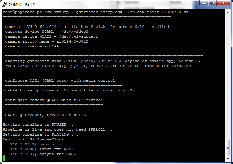
Call of “colcam-fbdev_1280x720.sh” for VM-016-COL (AR0144) series (A live image should show on the display)
All camera/video components get a separate "dev/v4l-subdev[x]" device.
The v4l2 capabilities are shown if you type: "v4l2-ctl -d [device] -L" e.g. "v4l2-ctl -d /dev/v4l-subdev1 -L".
For the first use, the camera and controller-camera interface must be configured with the tool v4l2-ctl. See chapter 5.
Scripts to Call C/C++ files Based on v4l2 Interface
After login, change into the directory: \v4l2_c-examples\..
cd v4l2_c-examples <ENTER>.
Now you can start working with the demo scripts.
Start the scripts with den word phrase "col" or "bw" depending on the connected camera color type.
- ar0144_col/bw_full_save-raw: scripts save a raw image from VM-016 in full resolution (8/10 and 12-Bit Formats are possible)
- ar052x_col/bw_full_save-raw: scripts save a raw image from VM-017/117 in full resolution (8/10 and 12-Bit Formats are possible)
To save the image, we use the program Yavta. Yavta stands for "Yet Another V4L2 Test Application". This is a test application based on V4L2 Linux interface.
Another way to use in your C-program is the direct access call to the v4l2 interface. For example:
v4l2-ctl -d0 --stream-mmap --stream-count 1 --stream-to=raw_image1.raw
For the first use, the camera and controller camera interface must be configured with the tool v4l2-ctl. See Scripts to Call C/C++ files Based on v4l2 Interface.
OpenCV Scripts
PHYTEC i.MX 8M Plus BSP PD21.1.0 includes OpenCV4.4. To use OpenCV with image output, we use window manager Wayland. PHYTEC tested OpenCV with PYTHON programming language. Examples of scripts can be found in the path “opencv-examples”:
- /opencv-examples/python/python3 phycam_video_v4l2.py: show the live image from the camera
- /opencv-examples/python/python3 face_detection.py: small application to detect faces
Tip
For the first use, the camera and controller-camera interface must be configured with the tool v4l2-ctl. See Scripts to Call C/C++ files Based on v4l2 Interface.
Configure Camera and Controller Camera Interface with “media-ctl”
Modern System-on-Chip (SoC) devices support a wide range of functionality in the way of internal hardware blocks which has resulted in a variety of ways to interconnect functions within the SoC that alter the V4L device content.
The Media Controller kernel API has been designed to expose detailed information about media devices and capture devices to userspace in a way that allows them to be interconnected in dynamic and complex ways at runtime.
Media controller devices expose entities to the media controller framework. Each entity has one or more source pads and one or more sink pads. You use the media controller kernel API (ie via media-ctl) to query entities, link source pads to sink pads, and set formats of pads.
We use media-ctl to set:
- the desired resolution and color format of the camera sensor
- the fitting resolution and color format in the CSI interface (controller-camera-interface)
- the way (and/or preprocessing) through the different hardware blocks in the controller
- the resulting camera stream is made available as “/dev/videox” device
These settings are necessary:
- once after restarting the system and using the camera for the first time
- set a new resolution, color format, or bit-depth
- set a new path through the hardware blocks
Following entities are present at the i.MX 8M Plus Image (check with “media-ctl –p”):
- entity 1: mxc_isi.0 (16 pads, 2 links)
pad0: Sink
...
pad11: Sink
pad12: Source
...
pad14: Source
pad15: Sink
- entity 18: mxc_isi.0.capture (1 pad, 1 link)
pad0: Sink
- entity 22: mxc-mipi-csi2.0 (8 pads, 2 links)
pad0: Sink
...
pad3: Sink
pad4: Source
...
pad7: Source
- entity 31: ar0144 2-0010 (1 pad, 1 link) #(depend on selected camera)
pad0: Source
To set the media-ctl, we use the following points in our demo script:
- media-ctl –r: reset all links to inactive
- media-ctl –l: setup the links between the hardware blocks
- media-ctl –V: formats the hardware blocks
For example, we will set the VM-016-COL (AR0144) with full Resolution from CSI Port to a /dev/videox device.
First, we set the links:
media-ctl -r
media-ctl -l "'ar0144 2-0010':0->'mxc-mipi-csi2.0':0[1]"
media-ctl -l "'mxc-mipi-csi2.0':4->'csi':0[1]"
media-ctl -l "'mxc_isi.0':12->'mxc_isi.0.capture':0[1]"
# Camera -> mxc-mipi-csi2.0 -> mxc_isi.0 -> mxc_isi.0.capture (/dev/videoX)
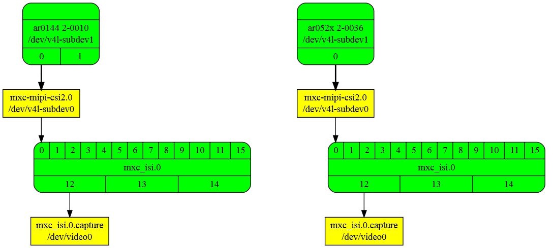
Video path VM-016 (AR0144) Video path VM-017 (AR052x)
Then, we format the hardware blocks:
media-ctl -V "'ar0144 2-0010':0 [fmt:SGRBG8_1X8/1280x800 (0,4)/1280x800]"
media-ctl -V "'mxc-mipi-csi2.0':4 [fmt:SGRBG8_1X8/1280x800]"
media-ctl -V "'mxc_isi.0':12 [fmt:SGRBG8_1X8/1280x800 field:none]"
Check the settings with “media-ctl –p”:

“media-ctl –p” Output
Now the camera is present at “dev/video0” device. The camera is ready for access.
Camera Features Configuration
v4l2-ctl Configuration
To set the various camera functions (e.g. exposure, gain, ...) use please the v4l2-ctl functions. You can get an overview of the existing functions by entering the commands:
- for example: v4l2-ctl -d /dev/v4l-subdev1 –all (list all)
- for example: v4l2-ctl -d /dev/v4l-subdev1 -L (list all detail)
With this control are many features usable, for example exposure. Set one exposure value (if the automatic disable):
- v4l2-ctl -d /dev/dev/v4l-subdev1 --set-ctrl=auto_exposure=1 (set AR0144 AEC off)
- v4l2-ctl -d /dev/dev/v4l-subdev1 --set-ctrl=exposure=800 (set the exposure time for a time, that the sensor need to generate 800 rows)
Camera Register Direct Configuration
To set or get a camera register directly, use the i2c functions in the path …/gstreamer-examples/tools/...
Note
Use this function only, if you know the register reaction. Read the register reference manual of the camera sensor manufacturer.
De-Bayering (demosaicking) with NEON CoProcessor
Most CMOS color chips provide the image in the Bayer mosaicing (Bayer raw) format. To get a color image in RGB format, it is necessary to convert the Bayer raw image.
These links detail how this can be done:
There also exist different algorithms for converting:
The microprocessor includes debayering hardware via ISP. However, the ISP is not supported yet. Therefore, you will have to do the converting via software. For this, you need additional processing power and the framerate will go down. It is better to use the NEON coprocessor of the i.MX 8M Plus. It is available as a GStreamer plugin "bayer2rgbneon" and in sources for use in an own C-program. PHYTEC supports a simple bilinear algorithm. The algorithm is very efficient and converts nearly in real-time.
To use in GStreamer, take the "bayer2rgbneon" plugin. For more information on "bayer2rgbneon" parameters type:
gst-inspect-1.0 bayer2rgbneon
The source is located at:
Revision History
Date | Version Numbers | Changes in this Manual |
08.07.2021 | L-1029e.A0 | Preliminary Manual |
| 28.10.2021 | L-1029e.A1 | Software updates |