Gesamtbetrag:
zzgl. Mwst.
BSP Manual - phyCORE-STM32MP15x (L-876e.A3)
Table of Contents
| Compatible BSP'S | BSP Release Type | BSP Release Date | BSP Status |
|---|---|---|---|
| PD21.2.1 | Minor Release | 10.12.2021 | Released |
Yocto Introduction
Our STM32MP1 BSP is based on OpenSTLinux Distribution: https://wiki.st.com/stm32mpu/wiki/OpenSTLinux_distribution
- To adapt the OpenSTLinux Distribution layer ("meta-st-openstlinux") to our board, we use our own Yocto layer, "meta-st-openstlinux-phytec". This layer extends the functionality of the meta-st-openstlinux distribution layer to enable features provided by our boards. With this layer, we also provide custom distros and images based on the one from OpenSTlinux.
- To adapt the STMicroelectronics BSP layer ("meta-st-stm32mp") to our board, we use our own Yocto layer, "meta-phytec/dynamic-layer/stm-st-stm32mp". This layer adapts the bootloaders (Trusted firmware + u-boot) and the Linux kernel to our Board.
You can find those layers in our git server below:
https://git.phytec.de/meta-st-openstlinux-phytec/
https://git.phytec.de/meta-phytec/tree/dynamic-layers/stm-st-stm32mp
Note
The meta-yogurt layer (PHYTEC custom distro layer) is not used with the OpenSTLinux BSP.
PHYTEC Documentation
PHYTEC will provide a variety of hardware and software documentation for all of our products. This includes any or all of the following:
- Quickstart Guide: A short guide on how to set up and boot a phyCORE board along with brief information on building a BSP, the device tree, and accessing peripherals.
- Hardware Manual: A detailed description of the System on Module and accompanying carrier board.
- Yocto Guide: A comprehensive guide for the Yocto version the phyCORE uses. This guide contains an overview of Yocto; introducing, installing, and customizing the PHYTEC BSP; how to work with programs like Poky and Bitbake; and much more.
- BSP Manual: A manual specific to the BSP version of the phyCORE. Information such as how to build the BSP, booting, updating software, device tree, and accessing peripherals can be found here.
- Development Environment Guide: This guide shows how to work with the Virtual Machine (VM) Host PHYTEC has developed and prepared to run various Development Environments. There are detailed step-by-step instructions for Eclipse and Qt Creator, which are included in the VM. There are instructions for running demo projects for these programs on a phyCORE product as well. Information on how to build a Linux host PC yourself is also a part of this guide.
- Pin Muxing Table: phyCORE SOMs have an accompanying pin table (in Excel format). This table will show the complete default signal path, from processor to carrier board. The default device tree muxing option will also be included. This gives a developer all the information needed in one location to make muxing changes and design options when developing a specialized carrier board or adapting a PHYTEC phyCORE SOM to an application.
On top of these standard manuals and guides, PHYTEC will also provide Product Change Notifications, Application Notes, and Technical Notes. These will be done on a case-by-case basis. Most of the documentation can be found on the applicable download page of our products.
Warning
Be aware that not all of the above documentation will be available for the phyBOARD-Sargas. To find all PHYTEC documentation, go to https://www.phytec.de/produkt/system-on-modules/phycore-stm32mp1-download/ or https://www.phytec.eu/product-eu/system-on-modules/phycore-stm32mp1-download/
BSP Introduction
Supported Hardware
This BSP supports the phyCORE-STM32MP1 SOM with phyBOARD-Sargas SBC. Visit our web page at:
https://www.phytec.de/produkt/system-on-modules/phycore-stm32mp1-download/
or
https://www.phytec.eu/product-eu/system-on-modules/phycore-stm32mp1-download/
Click the corresponding BSP release and look for the article number of your module in the column "Article Number". Finally, look for the correct machine name in the corresponding cell under "Machine Name".
Software and Software Requirements
- A modern Linux operating host system either natively or via a Virtual Machine.
- Ubuntu 20.04 LTS or 18.04 LTS (64-bit).
- VMWare Player and VirtualBox are possible solutions if you want to use a Virtual Machine.
- Virtual Machine (VM) configured for this BSP build environment can be downloaded at https://www.phytec.de/produkt/system-on-modules/phycore-stm32mp15x-download/#vm
- Root access to your Linux host PC. Some commands in this guide will not work if you do not have sudo access (e.g. package installation, formatting an SD card).
- At least 8GB of RAM (16GB or more is recommended).
- At least 100 GB of free space on the build partition of the host PC.
- An SD card reader, operational under Linux.
- An active internet connection.
For more details concerning Linux PC configuration, please refer to https://wiki.st.com/stm32mpu/wiki/PC_prerequisites
Getting Started with the Included SD Card
This section is designed to get the board up and running with the SD card included in the kit, which has been prepared with pre-built images.
Booting from the SD Card
This section describes how to boot the phyBOARD-Sargas with the pre-built images on the included SD card.
- Insert the micro SD card into the SD card slot of the board.
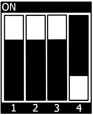
- Check that the S7 DIP switch is in the default position (boot from SD):

- Plug the USB cable into the USB debug on the board (X13) and your host PC. You should see two new devices appear: /dev/ttyUSB0 and /devttyUSB1. A Linux terminal will be accessible on /dev/ttyUSB0.
- Start your favorite terminal software (e.g. Minicom or Tera Term) on your host PC and configure it for 115200 baud, 8 data bits, no parity, and 1 stop bit (8n1) with no handshake.
- Example to launch minicom on /dev/ttyUSB0:
host:~$sudo minicom -D /dev/ttyUSB0
- Connect the power supply to the power connector.
The RGB LED (D11) will begin blinking BLUE as the board begins booting into Linux. The console output can be viewed in your terminal window. If everything was done correctly, the login prompt will be shown at the end of the booting process:
ST OpenSTLinux - Weston - (A Yocto Project Based Distro) 3.1-snapshot phycore-stm32mp1-3 ttySTM0
phycore-stm32mp1-3 login: root (automatic login)
root@phycore-stm32mp1-3:~#
Log in is done automatically as root (no password is required).
Building the BSP
This section will guide you through the general build process of the STM32MP1 BSP using our phyLinux script (based on repo tool) and the Yocto environment.
Basic Set-Up
There are a few important steps that have to be done before the main build process.
- Setting up the host: refer to OpenSTLinux documentation: https://wiki.st.com/stm32mpu/wiki/PC_prerequisites
Finding the Right Software Platform
The STM32MP1 BSP is a unified BSP, which means in the future it supports a set of different PHYTEC carrier boards (CB) with different Systems on Module (SOMs). These hardware sets are called MACHINE.
If you need to figure out the corresponding machine name of your board, go to https://www.phytec.de/produkt/system-on-modules/phycore-stm32mp15x-download/#software and click on the corresponding BSP release.
For our examples in this manual, we will use: <MACHINE>= phycore-stm32mp-3
Choose a BSP OpenSTLinux Distribution
The phyCORE-STM32MP1 BSP is based on OpenSTLinux which offers different distributions (DISTRO). When building the BSP, you have to choose one of them. The choice will depend on the features you want to get on your final application.
The available DISTROs are:
| DISTRO | Description |
| openstlinux-eglfs | OpenSTLinux featuring EGLFS (no X11, no Wayland). EGLFS is a platform plugin for running Qt5 applications on top of EGL and OpenGL ES 2.0, without an actual windowing system like X11 or Wayland. |
| openstlinux-weston | OpenSTLinux featuring Weston/Wayland display server protocol. |
| openstlinux-tiny | Distribution customized by PHYTEC for SOM equipped with small Flash memory size (128MB). It is based on OpenSTLinux distro with the following differences :
NOTE: currently, only BSP images proposed as an example only can be built with this DISTRO (no ST/PHYTEC support on this) |
For more details on the OpenSTLinux distributions, please refer to https://wiki.st.com/stm32mpu/wiki/OpenSTLinux_distribution#Distros
For our examples in this document, we will use: <DISTRO>= openstlinux-weston
Choose a BSP Image to be Build and Deployed
Once you have chosen a DISTRO, you have to choose a BSP Image to build and deploy on target. The available images depend on the DISTRO that has been chosen before.
| BSP Image | Description | Required DISTRO | MACHINE minimal FLASH memory size |
|---|---|---|---|
st-image-weston | OpenSTLinux Weston image with basic Wayland support - OpenSTLinux official image It comes with a graphical application demo that will show up on a Screen (if one display is connected to the carrier board). This is the image that is delivered by default with our standard evaluation kit. The Graphical demo is called "GTK demo launcher" and allows you to add additional custom applications that can be launched from this interface. More information on the available demo and how to add your own application can be found at this link: | openstlinux-weston | >= 1GB |
| st-image-core | OpenSTLinux core image (without Weston or any GUI framework) - OpenSTLinux supported image | any openstlinux DISTRO (except openstlinux-tiny) | >= 512MB |
| st-example-image-qt (sample image) | OpenSTLinux example of image based on QT framework over EGLFS - proposed as an example only | openstlinux-eglfs | >= 1GB |
| st-example-image-qt-wayland (sample image) | OpenSTLinux example of image based on QT framework over Weston/Wayland - proposed as an example only | openstlinux-weston | >= 1GB |
| st-image-core-minimal | PHYTEC OpenSTLinux core minimal image (PHYTEC custom image) - proposed as an example only It is based on st-image-core, but without :
| openstlinux-tiny | >= 128MB |
| st-example-image-qt-minimal (sample image) | PHYTEC OpenSTLinux example of image based on Qt minimal framework (PHYTEC custom image) - proposed as an example only | openstlinux-eglfs | >= 512MB |
For more information regarding OpenSTLinux images and how to create your own image, please refer to: https://wiki.st.com/stm32mpu/wiki/How_to_create_your_own_image
For our examples in this document we will use: <BSP_IMAGE>=st-image-weston
Get and Initialize the BSP Environment
- Create a fresh project directory:
host:~$ mkdir ~/PHYTEC_STM32MP1_BSP
- Get and Initialize the BSP Yocto environment with our phyLinux script:
host:~$ cd ~/PHYTEC_STM32MP1_BSP
host:~/PHYTEC_STM32MP1_BSP$ wget https://download.phytec.de/Software/Linux/Yocto/Tools/phyLinux
host:~/PHYTEC_STM32MP1_BSP$ chmod +x phyLinux
host:~/PHYTEC_STM32MP1_BSP$ ./phyLinux init
- On the first initialization, the phyLinux script will ask you to install the Repo tool in your /usr/local/bin directory.
- During the execution of the init command, you first need to choose the processor platform (SoC):
***************************************************
* Please choose one of the available SoC Platforms:
*
*   1: am335x
*   2: imx6
*   3: imx6ul
*   4: imx8
*   5: imx8m
*   6: imx8mm
*   7: nightly
*   8: rk3288
*   9: stm32mp1
*   10: topic
*
$
- Enter the choice number corresponding to stm32mp1 (9).
- Then choose the PHYTEC's BSP release number:
***************************************************
* Please choose one of the available Releases:
*
*   1: PD-BSP-Yocto-OpenSTLinux-STM32MP1-ALPHA1
*   2: PD-BSP-Yocto-OpenSTLinux-STM32MP1-ALPHA2
*   3: PD-BSP-Yocto-OpenSTLinux-STM32MP1-PD20.1.0
*   4: PD-BSP-Yocto-OpenSTLinux-STM32MP1-PD21.1.0
*   5: PD-BSP-Yocto-OpenSTLinux-STM32MP1-PD21.1.1
*   6: PD-BSP-Yocto-OpenSTLinux-STM32MP1-PD21.2.0
*   7: PD-BSP-Yocto-OpenSTLinux-STM32MP1-PD21.2.1
*
$
- The repo initialization will start
Tip
"ERROR 404" may appear during "repo init" command without any impact on the process.
- Once the repo initialization is finished, a popup will appear to will ask you to choose the DISTRO:

Press 'space' to select and press 'enter' to validate.
- Once the DISTRO is chosen, another popup will appear and will ask you to choose the MACHINE among all available PHYTEC platforms:

You must select one of the supported "phycore-stm32mp1-x" machines (PHYTEC phyCORE-STM32MP1).
Note
A new machine "phycore-stm32mp1-mx" was introduced with PD21.2.1 release. This doesn't correspond to any Phytec Hardware. It is a machine configuration template for using STM32CubeMX generated device tree. It works with the ST Yocto layer "meta-st-stm32mp-addons". Refer to section Build yocto machine from generated Device Tree to know how to use it.
- The STM32MP1 BSP depends on packages and firmware which are covered by a software license agreement (SLA). You will be asked to read and to accept this EULA:

Note
It is mandatory to accept this EULA to be able to use the internal STM32MP1 GPU.
- After accepting the EULA, the Shell Environment will be setup. The following message should appear:
[HOST DISTRIB check]
Linux Distrib: Ubuntu
Linux Release: 18.04

Required packages for Linux Distrib:
build-essential chrpath cpio debianutils diffstat gawk gcc-multilib git iputils-ping libegl1-mesa libgmp-dev libmpc-dev libsdl1.2-dev libssl-dev pylint3 python3 python3-git python3-jinja2 python3-pexpect python3-pip socat texinfo unzip wget xterm xz-utils

Check OK: all required packages are installed on host.

[DISTRO configuration]
Selected DISTRO: openstlinux-weston

[MACHINE configuration]
Selected MACHINE: phycore-stm32mp1-3

[source layers/openembedded-core/oe-init-build-env][from nothing]

[EULA configuration]

[Configure *.conf files]
[INFO] No 'site.conf.sample' file available at ~/PHYTEC_STM32MP1_BSP/layers/meta-st/scripts. Create default one...

Shell environment terminated. To activate the build environment in the current shell use:

    $ source openstlinux-init-phytec.sh


host:~/PHYTEC_STM32MP1_BSP$
OpenSTLinux Environment Setup
Note
The OpenSTLinux environment setup script is NOT sourced automatically when using the phyLinux tool.
This section describes the Build Environment Setup procedure that must be done after phyLinux execution and for each new terminal session.
- The build environment setup must be executed once per new terminal session, with the following command:
host:~/PHYTEC_STM32MP1_BSP$ source openstlinux-init-phytec.sh
A popup will appear to ask you to select one of the available Build directories:

You can choose to use one of the existing build environments (previously created) or you can choose to create a new build environment by selecting "NEW" (in case you want to use a new MACHINE and/or DISTRO)
Note
It is also possible to specify "DISTRO=x" and "MACHINE=x" in the command. In this case, the popup for MACHINE and DISTRO selection will not appear.
Example:
host:~/PHYTEC_STM32MP1_BSP$ DISTRO=openstlinux-weston MACHINE=phycore-stm32mp1-3 source openstlinux-init-phytec.sh
- After having selected the build environment, the OpenSTLinux Environment will be set up and you should now be in a sub-folder named '~/PHYTEC_STM32MP1_BSP/build-<DISTRO>-<MACHINE>':
[HOST DISTRIB check]
Linux Distrib: Ubuntu
Linux Release: 18.04

Required packages for Linux Distrib:
build-essential chrpath cpio debianutils diffstat gawk gcc-multilib git iputils-ping libegl1-mesa libgmp-dev libmpc-dev libsdl1.2-dev libssl-dev pylint3 python3 python3-git python3-jinja2 python3-pexpect python3-pip socat texinfo unzip wget xterm xz-utils

Check OK: all required packages are installed on host.

[BUILD_DIR configuration]
Selected BUILD_DIR: build-openstlinuxweston-phycore-stm32mp1-3

[source layers/openembedded-core/oe-init-build-env][with previous config]

===========================================================================
Configuration files have been created for the following configuration:

    DISTRO            :  openstlinux-weston
    DISTRO_CODENAME   :  dunfell
    MACHINE           :  phycore-stm32mp1-3
    BB_NUMBER_THREADS :  <no-custom-config-set>
    PARALLEL_MAKE     :  <no-custom-config-set>

    BUILDDIR          :  build-openstlinuxweston-phycore-stm32mp1-3
    DOWNLOAD_DIR      :  <disable>
    SSTATE_DIR        :  <disable>

    SOURCE_MIRROR_URL :  <no-custom-config-set>
    SSTATE_MIRRORS    :  <disable>

    WITH_EULA_ACCEPTED:  YES

===========================================================================

Available images for OpenSTLinux layers are:

  - Official OpenSTLinux images:
      st-image-weston       -   OpenSTLinux weston image with basic Wayland support (if enable in distro)

  - Other OpenSTLinux images:
      - Supported images:
          st-image-core         -   OpenSTLinux core image


You can now run 'bitbake <image>'

host:~/PHYTEC_STM32MP1_BSP/build-openstlinuxweston-phycore-stm32mp1-3$
Build Process
Now that the build environment is ready, you can start the first build process, using the following command:
host:~/PHYTEC_STM32MP1_BSP/build-openstlinuxweston-phycore-stm32mp1-3$ bitbake <BSP_IMAGE>
Example to build the "st-image-weston":
host:~/PHYTEC_STM32MP1_BSP/build-openstlinuxweston-phycore-stm32mp1-3$ bitbake st-image-weston
Generated BSP Image Binaries
All images generated by Bitbake are deployed to ~/PHYTEC_STM32MP1_BSP/build-<DISTRO>-<MACHINE>/tmp-glibc/deploy/images/<MACHINE>. The following list shows the generated files used for flashing the phycore-stm32mp1:
| Binary subfolder location | Binary file name | Description |
|---|---|---|
| arm-trusted-firmware | tf-a-<MACHINE>-serialboot.stm32 | TF-A binary for serial boot mode (STM32CubeProgrammer) |
| arm-trusted-firmware | tf-a-<MACHINE>-trusted.stm32 | TF-A binary for FSBL partition (trusted boot chain) |
| bootloader | u-boot-<MACHINE>-trusted.stm32 | U-Boot binary for SSBL partition (trusted boot chain) |
| - | st-image-bootfs-<DISTRO>-<MACHINE>.ext4 | Binary for bootfs partition on eMMC and microSD card devices |
| - | st-image-vendorfs-<DISTRO>-<MACHINE>.ext4 | Binary for vendorfs partition on eMMC and microSD card devices |
| - | <BSP_IMAGE>-<DISTRO>-<MACHINE>.ext4 | Binary for rootfs partition on eMMC and microSD card devices |
| - | st-image-userfs-<DISTRO>-<MACHINE>.ext4 | Binary for userfs partition on eMMC and microSD card devices |
| - | <BSP_IMAGE>-<DISTRO>-<MACHINE>_nand_x_x_multivolume.ubi | Binary for bootfs, vendorfs, rootfs, and userfs partitions on NAND device |
Programming the Target
In this section, we explain how to use the STM32MPCubeProgrammer tool to flash the NOR, eMMC, NAND, or SD Card.
Install STM32CubeProgrammer Tool
When using the PHYTEC Virtual Machine preconfigured for the phyCORE-STM32MP1 BSP, this tool is already installed. Otherwise, refer to https://wiki.st.com/stm32mpu/wiki/STM32CubeProgrammer for information on installing the STM32CubeProgrammer.
Connecting the Board via USB DFU Link
To download the BSP via DFU link, change the BOOT mode to UART/USB boot mode
- Switch OFF the board
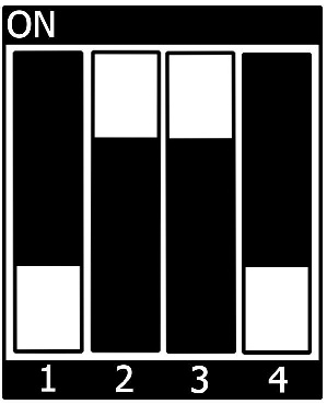
- Change the S7 DIP switch to UART/USB boot mode:
- Switch ON the board => The RED LED on the SOM must start blinking RED.
- Connect a USB micro-AB (OTG) to X12 and to the host PC that contains the downloaded image => The RED led should stop blinking.
Using STM32CubeProgrammer
- Go to the directory that contains the binaries and the flash layout files:
host:~$ cd ~/PHYTEC_STM32MP1_BSP/build-openstlinuxweston-stm32mp1/tmp-glibc/deploy/images/phycore-stm32mp1-3
- Get the device port location for the USB link:
$ STM32_Programmer_CLI -l usb
      -------------------------------------------------------------------
                        STM32CubeProgrammer <tool version>
      -------------------------------------------------------------------

=====  DFU Interface   =====

Total number of available STM32 device in DFU mode: 1

  Device Index           : USB1
  USB Bus Number         : 001
  USB Address Number     : 001
  Product ID             : DFU in HS Mode @Device ID /0x500, @Revision ID /0x0000
  Serial number          : 003C00283338510C34383330
  Firmware version       : 0x0110
Device ID : 0x0500- Use the flashing command:
$ STM32_Programmer_CLI -c port=<DEVICE_PORT_LOCATION> -w [<file.tsv>]
where
 w:
     Write
 <file.tsv>:PathToFlashlayout/flashlayout.tsv file
         if Flashlayout and binaries are not in the same directory, then the path to the Flashlayout files must be precised.
 <DEVICE_PORT_LOCATION>:
         e.g. usb1 (case sensitive)
Flashing the SD Card (Boot from SD-card)
To flash the SD Card with STM32CubeProgrammer:
- If not already done, insert an SD Card in the SD Card connector (X14).
- Use the flashing command with the following Flashlayout file: /flashlayout_st-image-weston/trusted/FlashLayout_sdcard_phycore-stm32mp1-3-trusted.tsv
$ STM32_Programmer_CLI -c port=usb1 -w flashlayout_st-image-weston/trusted/FlashLayout_sdcard_phycore-stm32mp1-3-trusted.tsv
This operation takes several minutes (mainly depending on the rootfs size). A successful flashing outputs the following message:
Flashing service completed successfully
Flashing the Target
Flashing the NOR and eMMC (Boot from NOR)
- Use the flashing command with the following Flashlayout file: /flashlayout_<BSP_IMAGE>/trusted/FlashLayout_nor-emmc_<MACHINE>-trusted.tsv
Tip
With this FlashLayout file, the ST Trusted Firmware and U-boot are downloaded into the NOR Flash. The kernel and rootfs files are downloaded into eMMC. This enables booting from NOR Flash and running Linux on the eMMC.
$ STM32_Programmer_CLI -c port=usb1 -w flashlayout_st-image-weston/FlashLayout_nor-emmc_phycore-stm32mp1-3-trusted.tsv
This operation takes several minutes (mainly depending on the rootfs size). A successful flashing outputs the following message:
Flashing service completed successfully
Flashing eMMC (Boot from eMMC)
- Use the flashing command with the following Flashlayout file: /flashlayout_<BSP_IMAGE>/trusted/FlashLayout_emmc_<MACHINE>-trusted.tsv
$ STM32_Programmer_CLI -c port=usb1 -w flashlayout_st-image-weston/FlashLayout_emmc_phycore-stm32mp1-3-trusted.tsv
This operation takes several minutes (mainly depending on the rootfs size). A successful flashing outputs the following message:
Flashing service completed successfully
Flashing NAND (Boot from NAND)
- Use the flashing command with the following Flashlayout file: /flashlayout_<BSP_IMAGE>/trusted/FlashLayout_nand_<MACHINE>-trusted.tsv
$ STM32_Programmer_CLI -c port=usb1 -w flashlayout_st-image-weston/FlashLayout_nand-2-256_phycore-stm32mp1-3-trusted.tsv
This operation takes several minutes (mainly depending on the rootfs size). A successful flashing outputs the following message:
Flashing service completed successfully
Create an SD Card Image (with PC Host SD Card Reader)
When booting from an SD card, another possibility (apart from using STM32Cubeprogrammer) is to create an SD Card image that contains all BSP binary files in correctly preformatted partitions. This image can be copied to the SD card easily using the single Linux command dd. Use the script create_sdcard_from_flashlayout.sh with the <FlashLayout file> = FlashLayout_sdcard_phycore-stm32mp1-3-trusted.tsv:
host:~$ cd build-<DISTRO>-<MACHINE>/tmp-glibc/deploy/images/<MACHINE>/scripts
host:~$ ./create_sdcard_from_flashlayout.sh ../flashlayout_<built-image>/trusted/<FlashLayout file>
Example:
host:~$ cd build-openstlinuxweston-phycore-stm32mp1-3/tmp-glibc/deploy/images/phycore-stm32mp1-3/scripts
host:~$ ./create_sdcard_from_flashlayout.sh ../flashlayout_st-image-weston/trusted/FlashLayout_sdcard_phycore-stm32mp1-3-trusted.tsv
The script will generate the following SD Card image (raw file): in the binaries directory: .../flashlayout_<BSP_IMAGE>_FlashLayout_sdcard_<MACHINE>-trusted.raw
Example : flashlayout_st-image-weston_FlashLayout_sdcard_phycore-stm32mp1-3-trusted.raw (in build-openstlinuxweston-phycore-stm32mp1-3/tmp-glibc/deploy/images/phycore-stm32mp1-3)
Use this raw file to populate the SD Card with dd command:
- Insert the uSD Card in the PC Host
- Umount all the partitions associated with uSD Card
- Populate microSD card with dd command:
host:~$ cd build-openstlinuxweston-phycore-stm32mp1-3/tmp-glibc/deploy/images/phycore-stm32mp1-3
host:~$ sudo dd if=flashlayout_st-image-weston_FlashLayout_sdcard_phycore-stm32mp1-3-trusted.raw of=/dev/mmcblk0 bs=8MB conv=fdatasync
More details can be found here: https://wiki.st.com/stm32mpu/wiki/How_to_populate_the_SD_card_with_dd_command
Warning
To create your bootable SD Card with the dd command, you must have root privileges. Because of this, you must be very careful when selecting the destination device for the dd command! All files on the selected destination device will be erased immediately without any further query! Consequently, having selected the wrong device can also erase your hard drive!
System Booting
The phyCORE-STM32MP1 can boot from the following devices:
- eMMC
- NOR
- NAND (when populated instead of eMMC)
- UART
- USB
- SD-Card
The boot source is chosen by setting the S7 DIP switch.
Booting from SD Card
Booting from the SD Card is useful in several situations (for example when the bootloader in Flash memory has crashed).
To boot from the SD card, set the S7 DIP switch as follow:
There are two ways to create a bootable SD card. You can either use:
- use a single prebuilt SD card image (see section Create an SD card image (with PC Host SD card reader))
- use STM32MPCubeprogrammer to flash the SD card from a target (see section Using STM32CubeProgrammer )
Booting from eMMC Flash
- First, you have to follow the procedure to flash the eMMC: Using STM32CubeProgrammer to Flash the BSP
- After flashing, power off the board. Then set the S7 DIP switch to the correct positions:

- When powering the board again, the system will boot from eMMC.
Booting from NOR Flash
- First, you have to follow the procedure to flash the NOR/eMMC: Using STM32CubeProgrammer to Flash the BSP
- After flashing, power off the board. Then set the S7 DIP switch to the correct positions:
- When powering the board again, the system will boot from NOR.
Booting from NAND Flash
- First, you have to follow the procedure to flash the NAND: Using STM32CubeProgrammer to Flash the BSP
- After flashing, power off the board. Then set the S7 DIP switch to the correct positions:

- When powering the board again, the system will boot from NAND.
Accessing Peripherals (in Linux userspace)
The following sections provide an overview of the supported hardware components and their operating system drivers on the STM32 platform.
UARTs (tty)
The STM32MP15x SoC provides up to 4 x UART and 4 x USART. phyCORE-STM32MP1 and carrier board is configured by default with 4 UARTs:
| UART interface | Linux Device | Function on Carrier Board | RTS/CTS |
|---|---|---|---|
| UART4 | /dev/ttySTM0 | USB debug (X13) - 1st FTDI serial port (Linux Terminal) | no |
| USART3 | /dev/ttySTM1 | USB debug (X13) - 2nd FTDI serial port
| no |
| USART1 | /dev/ttySTM2 | UART available on:
| yes |
Below are some Linux userspace commands to test the UART on target:
- Sending a message on USART3:
target$ echo "test" > /dev/ttySTM1
- Receiving a message on USART3:
target$ cat /dev/ttySTM1
- Be sure that the baud rate is set correctly on the host and target. In order to get the currently configured baud rate, you can use the command stty on the target.
Command to get tty help:
target$ tty --help
FD CAN Bus
For an overview of the Linux Controller Area Network (CAN) framework, please refer to https://wiki.st.com/stm32mpu/wiki/CAN_overview
Below are some examples of how to send or receive data on a SocketCAN interface using the can-utils package with the cansend and candump command:
Prerequisite: At least two nodes are required to communicate on a CAN network.
- Initialize CAN0 Link with 1Mbit/s:
target$ ip link set can0 up type can bitrate 1000000
- The command below allows you to get details on the created link:
target$ ip -details link show can0
2: can0: <NOARP,UP,LOWER_UP,ECHO> mtu 16 qdisc fq_codel state UNKNOWN mode DEFAULT group default qlen 10
    link/can  promiscuity 0
    can state ERROR-ACTIVE (berr-counter tx 0 rx 0) restart-ms 0
          bitrate 992063 sample-point 0.761
          tq 48 prop-seg 7 phase-seg1 8 phase-seg2 5 sjw 1
          m_can: tseg1 2..256 tseg2 1..128 sjw 1..128 brp 1..512 brp-inc 1
          m_can: dtseg1 1..32 dtseg2 1..16 dsjw 1..16 dbrp 1..32 dbrp-inc 1
clock 62500000numtxqueues 1 numrxqueues 1 gso_max_size 65536 gso_max_segs 65535- To send a single frame, use the cansend utility (cansend <device> <can_frame>):
target$ cansend can0 123#1122334455667788
- To receive CAN message, use the candump utility:
target$ candump can0
  can0  123   [8]  00 11 22 33 44 55 66 77
  can0  123   [8]  00 11 22 33 44 55 66 77
- To print help on candump utility, use: "candump -h"
Network
A gigabit Ethernet is provided by our module and board. The interfaces offer a standard Linux network port that can be programmed using theBSD socket interface. The BSP contains different Network tools that allow for the configuration and testing of the Ethernet connection.
For information about these different tools and how to use them, please refer tohttps://wiki.st.com/stm32mpu/wiki/Network_tools
Example of how to assign a given IP address to an Ethernet ETH0 interface:
ifconfig eth0 10.48.1.324
SD Card
The phyBOARD-Sargas supports a slot for Secure Digital Cards to be used as general-purpose block devices. These devices can be used in the same way as any other block device.
Warning
These kinds of devices are hot-pluggable. Nevertheless, you must ensure not to unplug the device while it is still mounted. This may result in data loss!
After inserting an SD/MMC card, the kernel will generate new device nodes in /dev. The full device can be reached via its /dev/mmcblk0 device node. SD/MMC card partitions will show up in the following way:
/dev/mmcblk0p<Y>
<Y> counts as the partition number starting from 1 to the max count of partitions on this device. The partitions can be formatted with any kind of file system and also handled in a standard manner, e.g. the mount and umount command work as expected.
GPIOs
The phyBOARD-Sargas carrier board has a set of pins specifically dedicated as user I/Os. Those pins are connected directly to STM32MP15x balls and are muxed as GPIOs. Accessing GPIOs from userspace can be done using the libgpiod.
To see how to access the GPIOs, please refer to https://wiki.st.com/stm32mpu/wiki/How_to_control_a_GPIO_in_userspace
Warning
Most of the CPU IOs are used for special functions. Before using a user IO, refer to the schematic or the hardware manual of your board to ensure that it is not already in use.
Keys
With gpio-keys driver, the Linux kernel can interpret GPIO signals as virtual keyboard events. The carrier board has 2 buttons (S4 and S5), which can be used with the gpio-keys driver.
To display the key events in ASCII format, use evtest.
- To show the available input devices, run:
target$ evtest
- You will get, for example:
No device specified, trying to scan all of /dev/input/event*
Available devices:
/dev/input/event0:      pmic_onkey
/dev/input/event1:      gpio-keys
Select the device event number [0-1]:
- Select input device event number 1 for gpio-keys:
Select the device event number [0-1]: 1
Input driver version is 1.0.1
Input device ID: bus 0x19 vendor 0x1 product 0x1 version 0x100
Input device name: "gpio-keys"
Supported events:
  Event type 0 (EV_SYN)
  Event type 1 (EV_KEY)
    Event code 28 (KEY_ENTER)
    Event code 102 (KEY_HOME)
Properties:
Testing ... (interrupt to exit)- Now you will see every hit on push buttons S4 (KEY_HOME) or S5 (KEY_ENTER):
Event: time 1570639195.409061, type 1 (EV_KEY), code 102 (KEY_HOME), value 1
Event: time 1570639195.409061, -------------- SYN_REPORT ------------
Event: time 1570639195.569047, type 1 (EV_KEY), code 102 (KEY_HOME), value 0
Event: time 1570639195.569047, -------------- SYN_REPORT ------------
Event: time 1570639196.809052, type 1 (EV_KEY), code 28 (KEY_ENTER), value 1
Event: time 1570639196.809052, -------------- SYN_REPORT ------------
Event: time 1570639197.009031, type 1 (EV_KEY), code 28 (KEY_ENTER), value 0
Event: time 1570639197.009031, -------------- SYN_REPORT ------------
- You can exit evtest with Ctrl+C
- Listening to the device with cat will print the raw output:
target$ cat /dev/input/event1
root@phycore-stm32mp1-3:/sys/class# cat /dev/input/event1
F
�]��fF
�]��F
�]BfF
�]B
LEDs
If any LEDs are connected to GPIOs, you have the possibility to access them by a special LED driver interface instead of the general GPIO interface (section GPIOs). You will then access them using /sys/class/leds/ instead of /sys/class/gpio/. The maximum brightness of the LEDs can be read from the max_brightness file. The brightness file will set the brightness of the LED (taking a value from 0 up to max_brightness). Most LEDs do not have hardware brightness support and therefore, will just be turned on by all non-zero brightness settings.
Here is a simple example:
- To get all LEDs available, type:
target$ ls /sys/class/leds
blue-power  pca:green:power  pca:red:power
Here the LEDs are the three possible colors from RGB lED driven by a LED dimmer present on the carrier board. By default, the RGB LED blinks blue (it is the "Linux Heartbeat" that shows the Linux Kernel is running). But this RGB LED can also be used as a "user LED".
- Example to toggle the RGB LED Blue color OFF:
target$ cd /sys/class/leds
target$ echo 0 >  blue-power/brightness
- Example to toggle RGB LED Blue color ON with a brightness=10:
target$ echo 10 > blue-power/brightness
- Example to toggle RGB LED Green color ON with a brightness=20:
target$ echo 20 > pca\:green\:power/brightness
I2C Bus
The STM32MP15x SoC provides up to 6 I²C FM (Fast-Mode). The phyCORE-STM32MP1 is configured with two Fast-Mode I²C modules called I2C4 and I2C1.
- I2C4 is reserved for the I²C devices on the module (PMIC, RTC, EEPROM).
- I2C1 is reserved for the carrier board which provides plenty of different I²C devices connected to the I²C1 bus of the STM32MP15x.
This section will describe basic device usage.
EEPROM
It is possible to read and write directly to the device:
/sys/class/i2c-dev/i2c-1/device/1-0050/eeprom
- To read and print the first 1024 bytes of the EEPROM as a hex number, execute:
target$ dd if=/sys/class/i2c-dev/i2c-1/device/1-0050/eeprom bs=1 count=1024 | od -x
- To fill the whole EEPROM with zeros, use:
target$ dd if=/dev/zero of=/sys/class/i2c-dev/i2c-1/device/1-0050/eeprom bs=4096 count=1
This operation takes some time as the EEPROM is relatively slow.
RTC
RTCs can be accessed via /dev/rtc*.
- Check the available RTC:
target$ ls /sys/class/rtc
target$ rtc0  rtc1
Tip
This will list all RTCs including the non-I²C RTCs.
- To find the name of the RTC devices, you can read its sysfs entry with:
target$ cat /sys/class/rtc/rtc*/name
rtc-rv3028 1-0052
stm32_rtc 5c004000.rtc
| RTC devices | Name | Description |
|---|---|---|
| /dev/RTC0 | rtc-rv3028 1-0052 | External RTC RV-3028 (on the SOM). It is the Default RTC used by Linux Timing System. |
/dev/RTC1 | stm32_rtc 5c004000.rtc | Internal RTC of the CPU |
As time is set according to the value of rtc0 during system boot, rtc0 should always be the RTC that is being backed up.
- Date and time can be manipulated with the date command and the hwclock tool. Example to set the date on /dev/RTC0:
target$ date 1010123119
Thu Oct 10 12:31:00 UTC 2019
target$ hwclock -w
Tip
As the VBACKUP pin of the external RTC component RV-3028 (on the SOM) is connected to a Gold Cap (on the carrier board), the date and time stored in the RTC are kept even if the board is switched off.
SPI Bus
The STM32MP1 SoC provides up to 6 SPI interfaces. The phyCORE-STM32MP1 is configured with 1 SPI called SPI16 (configured as SPI1 or SPI6).
By default, the Linux SPI driver used in the BSP is spidev.
| SPI interface | Linux Device |
|---|---|
SPI1 (or SPI6) | /dev/spidev0.0 |
USB Host and OTG
Both USB Host and OTG use the same framework.
To learn about the Linux USB framework and how to use it, please refer to the USB framework: https://wiki.st.com/stm32mpu/wiki/USB_overview
For more software details about the OTG internal peripheral, please refer to https://wiki.st.com/stm32mpu/wiki/OTG_internal_peripheral
For more software details about the USBH internal peripheral, please refer to https://wiki.st.com/stm32mpu/wiki/USBH_internal_peripheral
Create an SSH Connection with USB OTG or Ethernet
When the target is running on Linux, you can create an SSH connection with Ethernet or USB OTG (Ethernet point to point).
To create an SSH connection over USB OTG, proceed as follow:
- Plug a USB-A male to USB Micro B between the carrier board (X12) and the PC Host.
- On your host PC, with your network manager or using "ifconfig" on a terminal, check that there is a new network interface (ex: new interface called "enp0s20f0u2u3").
- Check the IP address of the USB OTG device of the target (usb0). By default, it is configured to 192.168.7.1.
target$ ifconfig
eth0      Link encap:Ethernet  HWaddr 8E:C5:2C:68:CF:75
          inet6 addr: fe80::8cc5:2cff:fe68:cf75/64 Scope:Link
          UP BROADCAST RUNNING MULTICAST  MTU:1500  Metric:1
          RX packets:0 errors:0 dropped:0 overruns:0 frame:0
          TX packets:35 errors:0 dropped:0 overruns:0 carrier:0
          collisions:0 txqueuelen:1000
          RX bytes:0 (0.0 B)  TX bytes:7597 (7.4 KiB)
          Interrupt:61 Base address:0x2000

lo        Link encap:Local Loopback
          inet addr:127.0.0.1  Mask:255.0.0.0
          inet6 addr: ::1/128 Scope:Host
          UP LOOPBACK RUNNING  MTU:65536  Metric:1
          RX packets:264 errors:0 dropped:0 overruns:0 frame:0
          TX packets:264 errors:0 dropped:0 overruns:0 carrier:0
          collisions:0 txqueuelen:1000
          RX bytes:16800 (16.4 KiB)  TX bytes:16800 (16.4 KiB)

usb0      Link encap:Ethernet  HWaddr BA:15:19:D5:BC:01
          inet addr:192.168.7.1  Bcast:192.168.7.255  Mask:255.255.255.0
          UP BROADCAST MULTICAST  MTU:1500  Metric:1
          RX packets:0 errors:0 dropped:0 overruns:0 frame:0
          TX packets:0 errors:0 dropped:0 overruns:0 carrier:0
          collisions:0 txqueuelen:1000
RX bytes:0 (0.0 B) TX bytes:0 (0.0 B)- On your host PC, with your network manager or with ifconfig command, check that there is a new network interface (ex: new interface called "enp0s20f0u2u3"). Then, configure the IP that matches with the usb0 target interface (192.168.7.1). Example with ifconfig:
host:~$ sudo ifconfig enp0s20f0u2u3 192.168.7.2
- Connect to the target (to create a new remote terminal through SSH):
host:~$ ssh root@192.168.7.1
- You can also copy any file from the host to the target with the following command:
host:~$ scp ~/myFile root@192.168.7.1:/home/root
The same procedure can be applied with an Ethernet connection, except that no Ethernet IP is attributed by default on the target (when no DHCP server is used). So you first have to set an Ethernet IP address to the target.
Audio
On the phyCORE-STM32MP1, we use the TI TLV320AIC3007 audio codec. Audio support is done via the SAI2 interface and controlled via I2C.
- To check if your sound card driver is loaded correctly and to check which audio output device is available:
target$ aplay -L
- You will get output similar toː
null
      Discard all samples (playback) or generate zero samples (capture)
pulse
      PulseAudio Sound Server
default
      Default ALSA Output (currently PulseAudio Sound Server)
sysdefault:CARD=STM32MP1PHYCORE
      STM32MP1-PHYCORE,
       Default Audio Device
- To test Audio Playback:
target$ aplay -D plughw:CARD=STM32MP1PHYCORE /usr/share/sounds/alsa/Front_Center.wav
- To list audio capture devices:
target$ arecord -l
**** List of CAPTURE Hardware Devices ****card 0: STM32MP1PHYCORE [STM32MP1-PHYCORE], device 1: 4400b004.audio-controller-tlv320aic3x-hifi tlv320aic3x-hifi-1 []
Subdevices: 1/1 Subdevice #0: subdevice #0
- Run speaker-test to identify channel numbers (Left, Right...). Example to check right and left channel (2 channels):
target$ speaker-test -c 2 -t wav
- You may have to select the audio device:
target$ speaker-test -c 2 -t wav -D plughw:CARD=STM32MP1PHYCORE
- To inspect your sound cards capabilities, call:
target$ alsamixer -c STM32MP1PHYCORE
You should see a lot of options as the audio-ICs has many features you can play with. It might be better to open alsamixer via ssh (see Create an SSH Connection with USB OTG or Ethernet) instead of the serial console, as the console graphical effects are better.
Audio Sources and Sinks
The phyBOARD-Sargas carrier board has three jacks: headphone (X28), line-in (X27), line out (X26); and one Mono speaker output connector (X5). Enabling and disabling input and output channels can be done with the alsamixer program.
With the Tabulator key, you can switch between the following screens: Screen Playback; Screen Capture. To enable or disable switchable controls, press m (mute). With the cursor keys left and right, you can step through the different channels. You can leave alsamixer by pressing the ESC key. The settings are saved automatically on shutdown and restored on boot by the systemd service alsa-restore. If you want to save the mixer settings manually, you can execute alsactl store. The settings are saved in /var/lib/alsa/asound.state.
Playback
To playback simple audio streams, you can use aplay. For example:
target$ aplay /usr/share/sounds/alsa/Front_Center.wav
#OR you may have to select the audio device:
target$ aplay -D plughw:CARD=STM32MP1PHYCORE /usr/share/sounds/alsa/Front_Center.wav
Capture
arecord is a command-line tool for capturing audio streams that use Line In as the default input source. The following example captures the current stereo input source with a sample rate of 48000 Hz and creates an audio file in WAV format (signed 16 bit per channel, 32 bit per sample):
target$ arecord -t wav -c 2 -r 48000 -f S16_LE test.wav
#OR :
target$ arecord -t wav -c 2 -f dat test.wav
#OR you may have to select the audio device:
target$ arecord -t wav -c 2 -f dat test.wav -D hw:0,1
Capturing can be stopped using CTRL-C. You can also specify the capture duration with the -d option.
- To play the recorded file:
target$ aplay test.wav
Texas Instruments TLV320AIC3007
The TI chip has a lot of mixing features as you will notice when opening alsamixer. To get an idea of the possibilities, refer to the datasheet from TI. One important feature is the analog mixing capability. You can route input channels to output channels, either active or passive, without transferring data back and forth to the SoC. This is usually known as zero-latency monitoring in terms of PC Audio cards. To control this feature, open alsamixer and go to Playback section (F3). There will be one group of selectors for each output channel, e.g. Right Line Mixer. For most of the input paths, you can select between "passive through" or you can activate a programmable gain signal path. To route the line input to the line output, activate both "Right Line Mixer PGAR Bypass" and "Left Line Mixer PGAL Bypass". You should now hear the input signal at the line-out.
As an example application, we can route the audio stream through the whole system. First, we deactivate the direct loop from line-in to line-out in alsamixer and activate the ADC for the analog input mixer and the DAC for the analog output mixer. We can now close the signal path in the user space by using a pipe and the ALSA tools:
target$ arecord -c 2 -r 48000 -f S16_LE | aplay
#OR
target$ arecord -c 2 -r 48000 -f S16_LE -D hw:0,1 | aplay -D plughw:CARD=STM32MP1PHYCORE
We created the following audio routing path:
analog in -> ADC -> STM32MP1 -> kernel -> (userspace -> kernel -> )* DAC -> analog out
* actually twice for the pipe
You should now hear the input signal at the line output again. But this time, the routing through the entire system added latency of 750 ms to the signal. The line mixer on the other side will only add about 4 μs delay.
This pipe routing is a crude example of how to use audio. If you need good audio performance, you should use an audio server. There are two prominent choices available, pulseaudio and jack.
As a third option, you can route the audio from line-in to the internal ADC. But instead of taking the signal path through the complete system, you can use the internal digital mixer of the TLV to directly route the signal back to the DAC and then to the output analog mixer and line-out. This signal path is record-only. You do not have the option of full-duplex playback in this mode. You can, however, use all the available DSP features of the TLV, the automatic gain, the high-pass filter, EQ, and de-emphasis filters for the record path. To activate this mode, you have to use the TI Windows tool to look up the specific I²C commands. The software can be found on the TI webpage and is called TLV320AIC3107EVM-K - GUI software. The 3107 is register compatible with all available features to the 3007. The software is used for both chips.
Displays
Three different kinds of displays are currently supported:
- HDMI monitor => with PEB-AV-01 PHYTEC addon connected on Audio/Video connectors X24/X25
- AC158 7" EDT capacitive LCD screen - 800x480 pixels => with PEB-AV-02 PHYTEC addon connected on Audio/Video connectors X24/X25
- MB1407 MIPI DSI screen - 4" TFT 480x800 pixels (from STMicroelectronics : https://wiki.st.com/stm32mpu/wiki/MB1407) => connected on MIPI DSI connector X41
- Official Raspberry Pi Touch 7" Display => connected on MIPI DSI connector X41
By default, the PHYTEC BSP is configured for the AC158 LCD parallel display (with PEB-AV-02 expansion). Switching between those 4 different configurations is explained in the next section.
Changing the BSP Display Configuration
Changing the BSP display configuration can be done enabling/disabling one of the following Linux Kernel device tree overlay:
- phyboard-stm32mp1-peb-av01-hdmi.dtbo
- phyboard-stm32mp1-peb-av02-lcd.dtbo
- phyboard-stm32mp1-dsi-lcd-mb1407.dtbo
- phyboard-stm32mp1-dsi-rpi-official-display.dtbo
By default, phyboard-stm32mp1-peb-av02-lcd device tree overlay is enabled.
Note that only one display expansion can be enabled at a time.
- To enable/disable one of those device tree expansions, refer to How to apply the device tree overlay.
- Once you have activated the corresponding device tree overlay, you can check that the display configuration is correct with the following command:
target$ modetest -M stm -c
Connectors:
id      encoder status          name            size (mm)       modes   encoders
29      28      connected       HDMI-A-1        520x290         2       28
  modes:
        name refresh (Hz) hdisp hss hse htot vdisp vss vse vtot)
  1024x768 70 1024 1048 1184 1328 768 771 777 806 75000 flags: nhsync, nvsync; type: driver
  800x600 72 800 856 976 1040 600 637 643 666 50000 flags: phsync, pvsync; type: driver
  props:
        1 EDID:
                flags: immutable blob
                blobs:

                value:
                        00ffffffffffff005a6330b701010101
                        201a010380341d782e0bd5a25750a128
                        0f5054bfef80b300a940a9c095009040
                        8180814081c0023a801871382d40582c
                        450009252100001e000000ff0055454a
                        3136333232313038340a000000fd0032
                        4b185213000a202020202020000000fc
                        00564132343635205345524945530081
        2 DPMS:
                flags: enum
                enums: On=0 Standby=1 Suspend=2 Off=3
                value: 0
        5 link-status:
                flags: enum
                enums: Good=0 Bad=1
                value: 0
        6 non-desktop:
                flags: immutable range
                values: 0 1
                value: 0
        19 CRTC_ID:
                flags: object
                value: 32
This command allows the user to check the display connectors and their status. modetest is DRM/KMS test tool.
The '-c' modetest option displays only the Connectors. To check all the Linux DRM display parameters (Encoders, CRTCs, Planes, Framerbuffers) use the command:
target$ modetest -M stm
To get more information about the modetest command and the Linux DRM/KMS display, graphic and composition framework, please refer to: https://wiki.st.com/stm32mpu/wiki/DRM_KMS_overview#Show_display_overall_status
Expected results to check that the display configuration on target is correct:
- HDMI configuration enabled: connector name = "HDMI-A-1", status ="connected"
- parallel LCD configuration enabled: connector name = "DPI-1", status ="connected"
- MIPI DSI display configuration enabled: connector name = "DSI-1", status ="connected"
Warning
- If you want to test displays or set specific video modes with the modetest tool, the Wayland/Weston framework has to be stopped with the following command:
systemctl stop weston@root.service
- If you want to restart Wayland, use the following command:
systemctl start weston@root.service
- If Wayland/Weston framework is not running but the splash screen is displayed, this one must be removed with the following command:
psplash-drm-quit
Selecting the HDMI Monitor Video Modes
To get the supported video modes (resolutions and refresh frequencies) of an HDMI monitor connected to the phyCORE-STM32MP platform, please refer to https://wiki.st.com/stm32mpu/wiki/How_to_display_on_HDMI#Video_modes and https://wiki.st.com/stm32mpu/wiki/How_to_display_on_HDMI#FAQ.
Example to set a particular HDMI video mode:
Taking the result of the "modetest -M stm -c" command from the previous section, we can see that:
- HDMI-A-1 is on connector id 29, is connected, and supports a resolution of 1280x720-50.
- associated CRTC is on id 32
The command to set the supported "800x600-72" video mode is:
target$ modetest -M stm -s 29@32:800x600-72 -d
Note
To be able to use this command, stop any running graphical environment on top of DRM/KMS Linux framework (like Wayland Weston or splash screen).
Generally, the HDMI monitor (or TV) provides (through I2C) several video modes (resolutions and refresh frequencies), that might not be all supported by the platform. In case all video modes supported by the monitor are rejected by the phyCORE-STM32MP platform, you will not be able to use the monitor.
One solution, in this case, is to use Linux kernel DRM KMS Helper with EDID Firmware files to be able to get more video modes possibilities and choose the HDMI resolution to apply. This EDID firmware is installed by default in the BSP. The resolution must be set in u-boot, setting the variable environment "hdmi_resolution" as follow.
example to fix the HDMI resolution to 1280x720 in u-boot:
STM32MP> setenv hdmi_resolution HDMI-A-1:edid/1280x720.bin
STM32MP> saveenv
By default, this environment variable does not exist in u-boot so that this EDID Firmware is not used for HDMI resolution configuration (resolution provided by the monitor and supported by the STM32MP are used).
The list of available EDID resolution binaries can be found on target in linux under: /lib/firmware/edid/. Note that not all of them are not supported by the STM32MP1.
Once you have saved the u-boot environments with "saveenv", you can continue the normal boot with the u-boot command "boot".
WLAN / Bluetooth Module Expansion
Two different WLAN / Bluetooth modules are supported :
- Laird Stering-LWB 2.4GHz or 5Ghz from Laird™ => with PEB-WLBT-05 PHYTEC addon connected on Expansion connector X33
- AMPAK AP6212A => with the Raspberry PI HAT "RedBear IoT pHAT v1.0" connected on Raspberry Pi connector X7
By default, the PHYTEC BSP is configured without any Wifi/Bluetooth module activated in the device tree. Activating Wifi/Bluetooth modules is explain in the next section.
Enabling WLAN / Bluetooth Module
Activating WLAN / Bluetooth module can be done by enabling one of the following Linux Kernel device tree overlay:
| Expansion | Function | Device tree overlay | |
|---|---|---|---|
PEB-WLBT-05[1] | Bluetooth[2] | on USART1 | phyboard-stm32mp1-peb-wlbt-05-bluetooth-usart1.dtbo |
| on USART3 | phyboard-stm32mp1-peb-wlbt-05-bluetooth-usart3.dtbo | ||
| WLAN | phyboard-stm32mp1-peb-wlbt-05-wlan.dtbo | ||
| RedBear IoT pHAT v1.0 | WLAN and Bluetooth | phyboard-stm32mp1-pi-hat-redbear.dtbo | |
| 1. | With PEB-WLBT-05, WLAN and Bluetooth features are independent (two different DT overlays), so it is possible to enable WLAN only, Bluetooth only, or both. |
| 2. | With PEB-WLBT-05, for Bluetooth, enable the device tree corresponding to the UART interface that should be used by the module (refer to the Application Note of this module to configure the phyBOARD-Sargas correctly). |
- To enable/disable one of those device tree expansions, refer to How to apply the device tree overlay.
Tip
- To get more information on setting up a WiFi connection, please refer to https://wiki.st.com/stm32mpu/wiki/How_to_setup_wifi_connection
- To get more information on setting up a Bluetooth connection and scan devices, please refer to https://wiki.st.com/stm32mpu/wiki/How_to_set_up_a_Bluetooth_connection and https://wiki.st.com/stm32mpu/wiki/How_to_scan_Bluetooth_devices
Watchdog
The STM32MP includes a Watchdog circuit called "IWDG" (Independent WatchDoG) that is able to reset the board when the system hangs (due to software or hardware failures). The IWDG is clocked by an independent clock and stays active even if the main clock fails. In addition, the watchdog function is performed in the VDD voltage domain, allowing the IWDG to remain functional even in low-power modes.
Two independent watchdogs (IWDG1 and IWDG2) are dedicated to MPU:
- IWGG1 can only be allocated to the Cortex-A7 secure (to be used in the secure context by the customer application: this instance is not supported in OpenSTLinux distribution).
- IWDG2 can be allocated to the Cortex-A7 non-secure to be used with Linux Watchdog Timer (WDT) framework.
How to enable the IWDG2 and configure its timeout value
The IWDG2 watchdog is enabled by default in the phycore-stm32mp15-som.dtsi kernel device tree with a custom timeout value in seconds (timeout-sec):
&iwdg2 {
timeout-sec = <32>;
status = "okay";
};
By default, the Watchdog Timer Linux framework support and the IWDG support are activated in the Linux kernel. This configuration can be changed through the Menuconfig tool (Configure the kernel through Menuconfig):
Device Drivers --->
[*] Watchdog Timer Support --->
[*] Disable watchdog shutdown on close
[*] Update boot-enabled watchdog until userspace takes over
<*> STM32 Independent WatchDoG (IWDG) support
With the option "Update boot-enabled watchdog until userspace takes over" (enabled by default), the kernel will ping the watchdog as long as an application opens the /dev/watchdog file (used by systemd).
How to use the watchdog in Linux using systemd
systemd is able to use the Hardware watchdog to check for system hangs (when the system is running or during reboot). This feature is enabled by default, with the RuntimeWatchdogSec= option in the file system.conf in /lib/systemd/system.conf.d/00-systemd-conf.conf :
RuntimeWatchdogSec=30s
ShutdownWatchdogSec=10min
When RuntimeWatchdogSec is not set or equal to 0, the Watchdog is not used. Setting this option to a different value allows you to use it.
RuntimeWatchdogSec defines the timeout value of the watchdog, while ShutdownWatchdogSec defines the timeout when the system is rebooted. For more detailed information about hardware watchdogs under systemd refer to http://0pointer.de/blog/projects/watchdog.html.
To get more information on the IWDG internal peripheral please refer to:
https://wiki.st.com/stm32mpu/wiki/IWDG_internal_peripheral
https://wiki.st.com/stm32mpu/wiki/IWDG_device_tree_configuration
To get more information on the IWDG Linux Kernel support and how to use and trace/debug the WDT framework, please refer to:
https://wiki.st.com/stm32mpu/wiki/Watchdog_overview
Special Connectors Pinout Configuration
The following special connectors are available on the phyCORE-Sargas:
- Raspberry PI HAT
- Arduino Shields
- Motor Control
Those special connectors pinout can be configured in the Linux Kernel device tree overlays with the following dts files:
- phyboard-stm32mp1-pi-hat-extension.dts
- phyboard-stm32mp1-uno-r3-extension.dts
- phyboard-stm32mp1-motor-control.dts
By default, no device tree overlays for those specific connectors are enabled.
- To enable/disable one of those device tree expansions, refer to How to apply the device tree overlay.
- To modify and rebuild the device tree overlays (for example, to adapt the pinout configuration of one specific connector), please refer to Rebuilding the Kernel, Bootloader, or Trusted Firmware.
Rapsberry PI HAT Connector (X7)
This connector is compatible with the pinout of the standard Raspberry Pi HAT connector (https://pinout.xyz/). The pinout can be configured by pin muxing in the following device tree overlay file: phyboard-stm32mp1-pi-hat-extension.dts
Please refer to the phyCORE-STM32MP1 Hardware Manual section Raspberry Pi HAT Connector (X7) for the pinout of this connector.
Arduino Shields Connector (X3)
This connector is compatible with the standard Arduino pinout connector (https://www.arduino.cc/en/reference/board). The pinout can be configured by pin muxing in the following device tree overlay file: phyboard-stm32mp1-uno-r3-extension.dts
Please refer to the phyCORE-STM32MP1 Hardware Manual section Arduino Shields Connector (X3) for the pinout of this connector.
Motor Control Connector (X38)
This connector is compatible with the pinout of STM32 standard motor control power boards. It is also possible to connect X-NUCLEO-IHMx STM32 motor control expansions using X-NUCLEO-IHM09M1 adaptor: https://www.st.com/en/ecosystems/x-nucleo-ihm09m1.html. The pinout can be configured by pin muxing in the following device tree overlay files: phyboard-stm32mp1-motor-control.dts or phyboard-stm32mp1-motor-control-m4.dts.
phyboard-stm32mp1-motor-control-m4.dts is an example of device tree configuration when signals are used by the Cortex-M4 MCU.
Please refer to the phyCORE-STM32MP1 Hardware Manual section Motor Control Connector (X38) for the pinout of this connector.
Warning
By default phyboard-stm32mp1-motor-control.dtsi and phyboard-stm32mp1-motor-control-m4.dtsi are not included in the SRC_URI of the linux-stm32mp yocto recipe. So, to be able to compile them, you first have to modify this recipe to add the corresponding SRC_URI. Please refer to Modify the Kernel Device Tree to know how to do this.
BSP Customization
STM32MP1 BSP Device Tree Concept
All device tree documentation can be found under:
host:~/PHYTEC_STM32MP1_BSP/build-<DISTRO>-<MACHINE>/tmp-glibc/work/<MACHINE>-<DISTRO>-linux-gnueabi/linux-stm32mp/<x.y>-r0/<x.y>/<x.y.z>/Documentation/devicetree/bindings
<x.y> and <x.y.z> in the above path have to be replaced by the Linux Kernel version number (ex: 5.4-r0/5.4/5.4.56/).
An introduction of the device tree usage can be found in the Linux kernel: linux/Documentation/devicetree/usage-model.txt. The device tree files are used during boot time by the Trusted Firmware (TF-A), the Bootloader (U-Boot), by the Linux kernel.
STM32MP documentation about the STM32MP1 Device Tree can be found at:
- https://wiki.st.com/stm32mpu/wiki/Device_tree
- https://wiki.st.com/stm32mpu/wiki/STM32MP15_device_tree
As shown in the STM32MP1 device tree documentation, the device tree organization depends on whether you are using the "upstream device tree" or the device tree generated by the STM32CubeMX tool.
In this BSP customization chapter, we are presenting the "upstream device tree" organization. For the STM32CubeMX STM32MP1 device tree organization refers to The STM32CubeMX tool.
Note that in this STM documentation, the device tree file's name concerning the boards does not correspond to our PHYTEC boards but the concept is exactly the same. The device tree files for our boards start with "phycore" or "phyboard". Refer to the following section for the phyCORE and phyBOARD device tree file organization: phyCORE-STM32MP1 and phyBOARD-STM32MP1 device tree (upstream).
Device tree source files:
.dts: The device tree source (DTS) that can be processed by DTC (Device Tree Compiler) into a binary device tree called "device tree blob" (.dtb). This device tree blob can be parsed by the embedded software components: LinuxKernel, U-Boot, and TF-A.
For each SOM versions (MACHINE), it is assigned a .dts file (ex: phycore-stm32mp1-4.dts for MACHINE=phycore-stm32mp1-4).
.dtsi: Source files that can be included from a DTS file.
For example, our phycore-stm32mp1-x DTS (phycore-stm32mp1-x.dts files) include one of the following STM32MP15dtsi files (SoC specific) which are upstreamed to the communities:

Example for our MACHINE "phycore-stm32mp1-3" (equipped with a STM32MP157CAC SoC):
phycore-stm32mp1-3.dts includes the following STM32MP15 SoC dtsi: stm32mp157.dtsi + stm32mp15xc.dtsi + stm32mp15-pinctrl.dtsi + stm32mp15xxac-pinctrl.dtsi
STM32MP1 Pin Muxing
The STM32MP1 SoC contains many peripheral interfaces. In order to reduce package size and lower overall system cost while maintaining maximum functionality, many of the STM32MP1 terminals can multiplex up to 16 signal functions. The STM32MP1 BSP is based on the pin controller Linux kernel framework (pinctrl) with a specific pinctrl-stm32 driver. The configuration is performed in the device tree source (DTS).
Please refer to ST documentation to learn about pinctrl and how to configure it in the device tree:
- https://wiki.st.com/stm32mpu/wiki/Pinctrl_overview
- https://wiki.st.com/stm32mpu/wiki/Pinctrl_device_tree_configuration
phyCORE-STM32MP1 and phyBOARD-Sargas Device Tree (Upstream)
As seen in previous section, the DTS of the phycore-stm32mp1-x machines (phycore-stm32mp1-x.dts) contain the specific SoC dtsi files. In addition to those .dtsi, other dtsi are included to specify the Board Hardware specificities, which is split into two boards; the SOM and the Baseboard (one dtsi per board):
- SOM: phycore-stm32mp15-som.dtsi => contains the Hardware specificities common to all the phyCORE-STM32MP1 SOM declinations (machines)
- Baseboard: phyboard-stm32mp1.dtsi => contains the Hardware configuration of the phyBOARD-Sargas
Note
The hardware differences between the different phyCORE-STM32MP1 machines are set in the phycore-stm32mp1-x.dts files. This is done including different ddr configuration dtsi files (in U-boot and TF-A only), and enabling/disabling SoC features (like GPU or CAN) or SOM devices (like eMMC/NAND).
SOM and Baseboard dtsi includes others .dtsi files (for pin control for example).
Below is the complete list of our PHYTEC custom DTS files (.dts & .dtsi) for the phyCORE-STM32MP1 and phyBOARD-Sargas, used by each software component (Linux Kernel, U-Boot, and TF-A).
To know how to modify those sources and rebuild the BSP image, refer to the next sections.
| Sources | DTS files path | Machine (.dts) | phyCORE-STM32MP1 .dtsi files | phyBOARD-Sargas .dtsi files | ||
peripheral configuration | pin control | peripheral configuration | pin control | |||
Linux Kernel | arch/arm/boot/dts/ | phycore-stm32mp15-som.dtsi | phycore-stm32mp15-pinctrl.dtsi | phyboard-stm32mp1.dtsi | phyboard-stm32mp1-pinctrl.dtsi | |
| U-Boot | arch/arm/dts | phycore-stm32mp1-x.dts | Copied from kernel: phycore-stm32mp1-x.dts phycore-stm32mp15-som.dtsi Specific to u-boot: phycore-stm32mp1-x-u-boot.dtsi phycore-stm32mp1-common-u-boot.dtsi Specific to u-boot: phycore-stm32mp15-ddr3-x-y-z.dtsi (same as TF-A) | phycore-stm32mp15-pinctrl.dtsi (copied from kernel) | same dtsi files as kernel (copied from kernel) | same dtsi files as kernel (copied from kernel) |
| TF-A | fdts | phycore-stm32mp1-x.dts | Copied from kernel: phycore-stm32mp1-x.dts Partially copied from kernel: phycore-stm32mp15-som.dtsi Specific to TF-A: phycore-stm32mp15-ddr3-x-y-z.dtsi (same as u-boot) | phycore-stm32mp15-pinctrl.dtsi | - | - |
| 1. | With PEB-WLBT-05, WLAN and Bluetooth features are independent (two different DT overlays), so it is possible to enable WLAN only, Bluetooth only, or both. |
| 2. | With PEB-WLBT-05, for Bluetooth, enable the device tree corresponding to the UART interface that should be used by the module (refer to the Application Note of this module to configure the phyBOARD-Sargas correctly). |
Tip
- For more details on the phyCORE-STM32MP1 and phyBOARD-Sargas pin muxing configuration on the BSP, you can refer to the Hardware Manual and the Pinmuxing Excel file that can be downloaded at https://www.phytec.de/produkt/system-on-modules/phycore-stm32mp1-download/
- When customizing the BSP, the device tree (DTS) can also be automatically generated thanks to the STM32CubeMX tool (The STM32CubeMX tool)
phyBOARD-Sargas Device Tree Overlay
phyBOARD-Sargas add-ons (expansions, phyCAM, etc..), or specific connector configuration (like pin muxing examples for Raspberry PI HAT or Arduino Uno connectors) are managed by Device Tree Overlay(DTO).
DTOs are device tree blob fragments that allow specific parts of a Kernel device tree to be overridden on-the-fly, before booting the Kernel. This allow to make small changes without defining a new complete device tree or modifying the original one.
The phyBOARD-Sargas DTO defined the necessary Kernel device tree adaptation for the specific add-ons/connectors config. One or more DTO can be applied by u-boot over the machine device tree (DTB) before booting the kernel (through boot.scr.cmd script).
phyBOARD-Sargas DTO source files (.dts) are stored aside the others kernel device tree source files, in a subdirectory called "overlays", : arch/arm/boot/dts/overlays/
Like classic device tree, the Device Tree Overlay sources are processed by DTC (Device Tree Compiler), but into a binary with .dtbo extension. Those binaries are then stored on target under: /boot/overlays
List of phyBOARD-Sargas Device Tree Overlays
Category | Device Tree Overlay Name | Description |
|---|---|---|
Displays (select only one display interface at a time) | phyboard-stm32mp1-peb-av02-lcd | PEB-AV-02 LCD expansion board. |
phyboard-stm32mp1-peb-av01-hdmi | PEB-AV-01 HDMI expansion board. if HDMI machine feature enabled (enabled by default for all phyCORE-STM32MP1 machines). | |
phyboard-stm32mp1-dsi-lcd-mb1407 | MB1407 MIPI DSI screen. if MIPI-DSI machine feature enabled (not available for all phyCORE-STM32MP1 machines). | |
phyboard-stm32mp1-dsi-rpi-official-display | Official Raspberry Pi Touch 7" Display. if MIPI-DSI machine feature enabled (not available for all phyCORE-STM32MP1 machines). | |
Specific connectors (pin control and config examples) | phyboard-stm32mp1-pi-hat-extension | Raspberry PI HAT connector configuration example. Contains sdmmc3 config examples. |
phyboard-stm32mp1-uno-r3-extension | Arduino Uno R3 connector configuration example. Contains Timers Pinctrl and configuration examples. Note that other Timers and ADCs. for the Arduino Shield connector are settled in "phyboard-stm32mp1-motor-control.dtso" overlay. | |
phyboard-stm32mp1-motor-control | ST motor control connector configuration example for Cortex-A7. Contains Pinctrl examples for Timers and ADC when managed by Linux (Cortex-A7). (not compatible with PEB-AV-01/02). | |
phyboard-stm32mp1-motor-control-m4 | ST motor control connector configuration example for Cortex-M4. Contains Pinctrl examples for Timers and ADC when managed by Cortex-M4. (not compatible with PEB-AV-01/02). | |
Wireless expansions | phyboard-stm32mp1-peb-wlbt-05-wlan | PEB-AV-05expansion board - DT overlay to activate WLAN function. if WIFI machine feature enabled (enabled by default for all phyCORE-STM32MP1 machines). |
phyboard-stm32mp1-peb-wlbt-05-bluetooth-usart3 | PEB-AV-05expansion board - DT overlay to activate Bluetooth function, through USART3. (no CAN transceiver and no 2nd debug FTDI available on baseboard). if Bluetooth machine feature enabled (enabled by default for all phyCORE-STM32MP1 machines). | |
phyboard-stm32mp1-peb-wlbt-05-bluetooth-usart1 | PEB-AV-05expansion board - DT overlay to activate Bluetooth function, through USART1. (no RS232 transceiver available on baseboard). if Bluetooth machine feature enabled(enabled by default for all phyCORE-STM32MP1 machines). | |
phyboard-stm32mp1-pi-hat-redbear | Red Bear IoT pHAT (WLAN and Bluetooth) if WIFI or Bluetooth machine feature enabled(enabled by default for all phyCORE-STM32MP1 machines). | |
phyCAM-P | phyboard-stm32mp1-phycam-vm010-bw | phyCAM-P VM-010 B&W connected with 8bits data bus. |
phyboard-stm32mp1-phycam-vm010-col | phyCAM-P VM-010 COL connected with 8bits data bus. | |
phyboard-stm32mp1-phycam-vm010-bw-10bits | phyCAM-P VM-010 B&W connected with 10bits data bus. | |
phyboard-stm32mp1-phycam-vm010-col-10bits | phyCAM-P VM-010 COL connected with 10bits data bus. | |
RS485 | phyboard-stm32mp1-rs485 | DT overlay to enable RS485 at boot time. |
How to Apply the Device Tree Overlay
The board must be booted and accessible through a remote console. Device tree overlays can be applied either from u-boot or from userspace:
Applying DTO from userspace
- Edit the /boot/overlays/overlays.txt file
target$ vi /boot/overlays/overlays.txt
This file specifies the DT overlays to apply with the following syntax:
overlay=aa bb cc dd
- aa, bb, cc, dd correspond to a device tree name file (without extension) located on /overlays/ directory:
/overlays/aa.dtbo
/overlays/bb.dtbo
/overlays/cc.dtbo
/overlays/dd.dtbo
Edit the file to enable/disable any DTO located in the /overlays/ directory.
Tip
You will need to use the following basic vi command:
<Inser> or <i> => to enter Edit mode
Esc => to escape the Edit mode
:wq => save the modifications and quit the file
:q! => quit the file without saving
- force filesystem sync:
target$ sync
- reboot the board:
target$ reboot
Applying DTO from u-boot
Device tree overlays to apply can also be set on u-boot with the following commands:
STM32MP> setenv overlay 'aa bb cc'
STM32MP> saveenv
With aa, bb, cc, dd corresponding to a device tree name file (without extension) located on /overlays/ directory:
/overlays/aa.dtbo
/overlays/bb.dtbo
/overlays/cc.dtbo
/overlays/dd.dtbo
If you want to modify an existing overlay variable, you can use the following command:
STM32MP> editenv overlay
Once you have save the u-boot environments with "saveenv", you can continue the normal boot with the u-boot command "boot".
Note
This method will create the "overlay" u-boot env variable and in this case, the content of /boot/overlays/overlays.txt will be ignored.
To use the overlays.txt file instead, remove the "overlay" env var with following u-boot command: setenv overlay
Creating Custom Yocto Layer
Creating your layer should be one of the first tasks when customizing the BSP. In the following chapter, we have an embedded project called "racer" which we will implement using the OpenSTLinux distribution.
Create the layer
First, we need to create a new layer. Yocto provides a script for that. If you set up the BSP and the shell is ready, type:
host:~/PHYTEC_STM32MP1_BSP/build-<DISTRO>-<MACHINE>$ bitbake-layers create-layer meta-racer
The default options are fine for now. Move the layer to the source directory:
host:~/PHYTEC_STM32MP1_BSP/build-<DISTRO>-<MACHINE>$ mv meta-racer ../layers/
Create a Git repository in this layer to track your changes:
host:~/PHYTEC_STM32MP1_BSP/build-<DISTRO>-<MACHINE>$ cd ../layers/meta-racer
host:~/PHYTEC_STM32MP1_BSP/layers/meta-racer$ git init && git add . && git commit -s -m "create meta-racer"
Add the layer to the BSP build dependency
Now you can add the layer directly to your build-<DISTRO>-<MACHINE>/conf/bblayers.conf:
BBLAYERS += "${OEROOT}/layers/meta-racer"or with a script provided by Yocto:
host:~/PHYTEC_STM32MP1_BSP/layers/meta-racer$ cd ../../build-<DISTRO>-<MACHINE>
host:~/PHYTEC_STM32MP1_BSP/build-<DISTRO>-<MACHINE>$ bitbake-layers add-layer ../layers/meta-racer
Tip
Further resources: https://wiki.st.com/stm32mpu/wiki/How_to_create_a_new_open_embedded_layer
Configure the Kernel through Menuconfig
The process of building a kernel has two parts: configuring the kernel options and building the source with those options. For your BSP customization, you may have to change the kernel options. This section describes how to do it.
- Start the Linux kernel configuration menu:
host:~/PHYTEC_STM32MP1_BSP/build-<DISTRO>-<MACHINE>$ bitbake linux-stm32mp -c menuconfig
- Navigate forward or backward directly between feature
- un/select, modify feature(s) you want
- When the configuration is OK: exit and save the new configuration
Tip
useful Menuconfig keys to know:
enter: enter in config subdirectory
space: hit several times to either select [*], select in module [m], or unselect [ ]
/: to search for a keyword, this is useful to navigate in the tree
?: to have more information on the selected line
- After saving et exiting the menuconfig, the kernel the modifications made are only temporary. Only the kernel configuration file (.config) in the kernel build directory is updated. It is located under:
host:~/PHYTEC_STM32MP1_BSP/build-<DISTRO>-<MACHINE>/tmp-glibc/work/<MACHINE>-ostl-linux-gnueabi/linux-stm32mp/<x.y>-r0/build/
- Your modifications will be taken into account if the kernel is rebuilt from this point (without clean), but it will not be permanent (not in the Linux Kernel source directory). To save it, create a new configuration fragment that will contain only your configuration changes:
host:~/PHYTEC_STM32MP1_BSP/build-<DISTRO>-<MACHINE>$ bitbake linux-stm32mp -c diffconfig
- The fragment is generated under:
host:~/PHYTEC_STM32MP1_BSP/build-<DISTRO>-<MACHINE>/tmp-glibc/work/phycore_stm32mp1_x-ostl-linux-gnueabi/linux-stm32mp/<x.y>-r0/fragment.cfg
- You can temporarily save and rename this fragment to your home folder (for example):
host:~/PHYTEC_STM32MP1_BSP/build-<DISTRO>-<MACHINE>$ cp tmp-glibc/work/phycore_stm32mp1_x-ostl-linux-gnueabi/linux-stm32mp/<x.y>-r0/fragment.cfg ~/<custom-fragment>.cfg
- This configuration fragment file has to be added to the linux-stm32mp_%.bbappend yocto recipe (see Adding Kernel configuration fragment)
- Without using the new config fragment file, you can temporarily test your kernel configurations changes (build without clean) using the temporary method: Updating the kernel/device tree on running target (temporary method)
- If you need to remove/modify your kernel configuration changes previously made, you have to restart from a clean Linux Kernel build:
host:~/PHYTEC_STM32MP1_BSP/build-<DISTRO>-<MACHINE>$ bitbake linux-stm32mp -c cleansstate
With this clean, when using bitbake diffconfig command again, it will generate a new fragment comparing the new changes made from the default Linux Kernel configuration.
Patch Kernel, Bootloader, or Trusted Firmware
Modify the Sources with devtool
Instead of using the standard PHYTEC versions of kernel, bootloader, or trusted firmware which are provided in the Yocto recipes, you can modify the source code to build your customized BSP.
Modifying the kernel device tree is necessary when customizing your own application/baseboard (ex: pin muxing modification).
Devtool is a set of helper scripts to enhance the user workflow of Yocto. It is available as soon as you set up your shell environment. Devtool can be used to:
- modify existing sources
- integrate software projects into your build setup
- build software and deploy software modifications to your target
Devtool command to modify an existing recipe:
devtool modify -x <recipename> [<directory>]
- <recipename>: corresponding recipe names for kernel, bootloader, or trusted firmware are:
| Trusted Firmware | tf-a-stm32mp |
| Bootloader | u-boot-stm32mp |
| Kernel | linux-stm32mp |
- <directory>: optional parameter to specify the path where the source files will be located. If not specified, the following subdirectory will be created and used: ~/PHYTEC_STM32MP1_BSP/build-<DISTRO>-<MACHINE>/workspace/sources
Example for modifying the kernel:
host:~/PHYTEC_STM32MP1_BSP/build-<DISTRO>-<MACHINE>$ devtool modify -x linux-stm32mp sources/linux-stm32mp
Devtool will create a new Yocto layer in /build-openstlinuxweston-<MACHINE>/workspace where you can see all modifications done by devtool. It will extract the sources corresponding to the recipe to the specified directory. In this example kernel sources will be extracted on the following local git directory: /build-openstlinuxweston-<MACHINE>/sources/linux-stm32mp
A bbappend file will be created in the workspace directing the SRC_URI to this directory. Building an image with Bitbake will now use the sources in this directory. Now you can do your kernel, u-boot, or trusted-firmware modifications.
Example of modifying a kernel device tree file:
host:~/PHYTEC_STM32MP1_BSP/build-<DISTRO>-<MACHINE>$ vim sources/linux-stm32mp/arch/arm/boot/dts/phycore-stm32mp1-3.dtsi
Make a change in the dts file with your favorite code editor. When it is done, refer to the next sections for re-building the BSP:
- Re-build the kernel/BSP image, referring to the section Rebuilding the Kernel, Bootloader, or Trusted Firmware.
- For a quick test on a running target (temporary method), you can rebuild the kernel/device tree and only deploy the new device tree blob on target referring to Updating the kernel/device Tree on a Running Target (Temporary Method)
If you want to store your code changes permanently, it is advisable to create a patch from the changes, then store and backup only the patch. You can go into the linux-stm32mp directory and create a patch with the method described in the section Creating Patches.
Tip
Learn more about devtool at:
https://wiki.st.com/stm32mpu/wiki/OpenEmbedded_-_devtool
https://www.yoctoproject.org/docs/2.6/ref-manual/ref-manual.html#ref-devtool-reference
Learn more about how to modify Linux Kernel, U-Boot, and TF-A at https://wiki.st.com/stm32mpu/wiki/How_to_cross-compile_with_the_Distribution_Package.
Updating the kernel/device Tree on a Running Target (Temporary Method)
After modifying the device tree kernel and/or kernel configuration, you can test your modifications on your running target with the following quick but temporary method (to use for prototyping only).
- Rebuild kernel/device tree:
host:~/PHYTEC_STM32MP1_BSP/build-<DISTRO>-<MACHINE>$ bitbake linux-stm32mp
This command will generate a new Kernel Image (uImage) and new device tree blob (<MACHINE>.dtb) under the binaries folder (tmp-glibc/deploy/images/<MACHINE>)
- Create an SSH connection between your PC and the running board with Ethernet or USB OTG (see Create an SSH Connection with USB OTG or Ethernet)
- For device tree update: copy the new device tree blob to the /boot directory of the target:
host:~/PHYTEC_STM32MP1_BSP/build-<DISTRO>-<MACHINE>$ scp tmp-glibc/deploy/images/<MACHINE>/<MACHINE>.dtb root@<Target_IP>:/boot
Example:
host:~/PHYTEC_STM32MP1_BSP/build-openstlinuxweston-phycore-stm32mp$ scp tmp-glibc/deploy/images/phycore-stm32mp-3/phycore-stm32mp-3.dtb root@192.168.7.1:/boot
- For kernel update: copy the new kernel image (uImage) to the /boot directory of the target:
host:~/PHYTEC_STM32MP1_BSP/build-<DISTRO>-<MACHINE>$ scp tmp-glibc/deploy/images/<MACHINE>/uImage root@<Target_IP>:/boot
Example:
host:~/PHYTEC_STM32MP1_BSP/build-openstlinuxweston-phycore-stm32mp$ scp tmp-glibc/deploy/images/phycore-stm32mp-3/uImage root@192.168.7.1:/boot
- Reboot the board with the following commands on target:
root@phycore-stm32mp1-3:~# cd /boot; sync; systemctl reboot
Rebuilding the Kernel, Bootloader, or Trusted Firmware
Launch the following command to re-start the BSP image build process (only the modules that have been modified will be re-generated; the kernel for example).
host:~/PHYTEC_STM32MP1_BSP/build-<DISTRO>-<MACHINE>$ bitbake <BSP_IMAGE>
For quick build tests, you may also want to build only the module you have modified (kernel, bootloader, or trusted firmware), as described in the following sections.
Tip
We recommend rebuilding the entire BSP image as described above, so that all necessary BSP binaries are generated, before flashing the target.
Rebuild the Kernel (kernel image + device tree blob)
To rebuild the kernel only, launch the following command:
host:~/PHYTEC_STM32MP1_BSP/build-<DISTRO>-<MACHINE>$ bitbake linux-stm32mp
Rebuild the Bootloader
To rebuild the bootloader only, launch the following command:
host:~/PHYTEC_STM32MP1_BSP/build-<DISTRO>-<MACHINE>$ bitbake u-boot-stm3mp
Rebuild the Trusted Firmware
To rebuild the trusted firmware only, launch the following command:
host:~/PHYTEC_STM32MP1_BSP/build-<DISTRO>-<MACHINE>$ bitbake tf-a-stm32mp
Rebuild Kernel Device Tree Overlay
To rebuild kernel device tree overlay, launch the following command:
host:~/PHYTEC_STM32MP1_BSP/build-<DISTRO>-<MACHINE>$ bitbake phytec-dt-overlays-stm32mp -c cleanall
host:~/PHYTEC_STM32MP1_BSP/build-<DISTRO>-<MACHINE>$ bitbake phytec-dt-overlays-stm32mp
Creating Patches
You have to create the patch from the local git directory containing the modified source code (directory created by devtool).
Example to Create a Kernel Patch
- Enter to the <local git directory>:
host:~/PHYTEC_STM32MP1_BSP/build-openstlinuxweston-phycore-stm32mp1-3$ cd sources/linux-stm32mp
host:<local git directory>$ cd sources/linux-stm32mp
host:<local git directory>$ git status                        # Show changes files
host:<local git directory>$ git diff                          # Show all the changes made compared to the previous commit
host:<local git directory>$ git add .                         # Add all modified file to the staging area
host:<local git directory>$ git commit -m "DTS modification"  # Creates a commit with a not so useful commit message
host:<local git directory>$ git format-patch -1 -o ~/         # Creates a patch of the last commit and saves it in you home directory
/home/<user>/0001-DTS-modification.patch
The created patch is the home directory: host:~/0001-DTS-modification.patch.
Applying Patches
The created patches can be used once you have validated your device tree modifications (using devtool for example) and you want to customize the BSP by adding a custom Yocto layer (how to create a Yocto layer is described in Creating Custom Yocto Layer).
Tip
It is possible to add your patches directly in the meta-phytec layer, but it is not recommended to do this, as it is easier to maintain your custom BSP if you have your own Yocto layer (particularly when we deliver BSP updates).
Warning
Before being able to apply any patch to a recipe, the recipe must be removed from the devtool workspace. To do that, use the following command (example for linux-stm32mp recipe):
devtool reset linux-stm32mp
This will remove the linux-stm32mp.bbappend file created by devtool in ../build-<DISTRO>-<MACHINE>/workspace/appends
Then clean the recipe build
bitbake linux-stm32mp -c cleansstate
After you have created the kernel patch, you must create a .bbappend file in your custom layer. The locations for the append recipes are:
| recipe (.bb) to append | .bbappend file path in custom layer to create |
| linux-stm32mp.bb | layers/<custom_layer>/recipes-kernel/linux/linux-stm32mp_%.bbappend |
| u-boot-stm32mp.bb | layers/<custom_layer>/recipes-bsp/u-boot-stm32mp/u-boot-stm32mp_%.bbappend |
| tf-a-stm32mp.bb | layers/<custom_layer>/recipes-bsp/trusted-firmware-a/tf-a-stm32mp_%.bbappend |
The following example is for the linux-stm32mp recipe. You have to adjust the paths:
- Create the folders and move the patch into it. Then create the bbappend file:
host:~/PHYTEC_STM32MP1_BSP/$ mkdir -p layers/meta-custom/recipes-kernel/linux/features                          # create the directories
host:~/PHYTEC_STM32MP1_BSP/$ cp ~/0001-DTS-modification.patch layers/meta-custom/recipes-kernel/linux/features  # copy patch in the features directory
host:~/PHYTEC_STM32MP1_BSP/$ touch layers/meta-custom/recipes-kernel/linux/linux-stm32mp_%.bbappend             # create a bbappend file
Warning
Pay attention to your current work directory. You have to execute the above commands in the BSP top-level directory. Not in the build directory!
- Use your favorite editor to add the following lines into the bbappend file (layers/meta-custom/recipes-kernel/linux/linux-stm32mp_%.bbappend):
FILESEXTRAPATHS_prepend := "${THISDIR}/features:"
SRC_URI_append = " \
file://0001-DTS-modification.patch \
"- Save the file, go back to the build directory and rebuild the kernel recipe with:
host:~/PHYTEC_STM32MP1_BSP/$ cd build-<DISTRO>-<MACHINE>
host:~/PHYTEC_STM32MP1_BSP/build-<DISTRO>-<MACHINE>$ bitbake linux-stm32mp -c cleansstate
host:~/PHYTEC_STM32MP1_BSP/build-<DISTRO>-<MACHINE>$ bitbake linux-stm32mp
- If the build is successful, you can then rebuild the entire image (st-image-weston for example).
Tip
Further resources: https://wiki.st.com/stm32mpu/wiki/How_to_customize_the_Linux_kernel
Adding Kernel Configuration Fragment
After creating one or more kernel configuration file (.cfg) with menuconfig and diffconfig bitbake commands (Configure the kernel through Menuconfig), you have to add them in the linux-stm32mp_%.bbappend recipe of your customer Yocto layer, so that it will be included in the final generated Kernel configuration file (.config file in the Kernel build directory).
Tip
It is possible to add your kernel config fragment files directly in the meta-phytec layer, but it is no recommended to do this, as it is easier to maintain your custom BSP if you have your own Yocto layer (particularly when we deliver BSP updates).
- If not already done, you must create a linux-stm32mp_%.bbappend file in your custom layer:
Replace <x.y> below with the kernel version x.y (ex: 5.4).
host:~/PHYTEC_STM32MP1_BSP/$ mkdir -p layers/meta-custom/recipes-kernel/linux/features/<x.y>                     # create the directories
host:~/PHYTEC_STM32MP1_BSP/$ touch layers/meta-custom/recipes-kernel/linux/linux-stm32mp_%.bbappend             # create a bbappend file
- Copy your config fragment file (<custom-fragment>.cfg) into the features/<x.y> directory (ex: features/4.19):
host:~/PHYTEC_STM32MP1_BSP/$ cp ~/<custom-fragment>.cfg layers/meta-custom/recipes-kernel/linux/features/<x.y> # copy fragment in the features directory
Warning
Pay attention to your current work directory. You have to execute the above commands in the BSP top-level directory. Not in the build directory!
- Use your favorite editor to add the following lines into the bbappend file (layers/meta-custom/recipes-kernel/linux/linux-stm32mp_%.bbappend):
FILESEXTRAPATHS_prepend := "${THISDIR}/features:"

SRC_URI += "file://${LINUX_VERSION}/custom-fragment.cfg;subdir=fragments"
KERNEL_CONFIG_FRAGMENTS += "${WORKDIR}/fragments/${LINUX_VERSION}/custom-fragment.cfg"- Save the file, go back to the build directory and rebuild the kernel recipe with:
host:~/PHYTEC_STM32MP1_BSP/$ cd build-<DISTRO>-<MACHINE>
host:~/PHYTEC_STM32MP1_BSP/build-<DISTRO>-<MACHINE>$ bitbake linux-stm32mp -c cleansstate
host:~/PHYTEC_STM32MP1_BSP/build-<DISTRO>-<MACHINE>$ bitbake linux-stm32mp
- If the build is successful, you can then rebuild the st-image-bootfs partition (containing the kernel and device tree) or the entire image (st-image-weston for example).
OpenSTLinux Yocto SDK
When a Yocto distribution has been modified and validated on target, it is pertinent to build a new Software Development Kit that integrates the modifications and redistributes this SDK to developers. This chapter describes the procedure to build, install and use the SDK.
For more details on the OpenSTLinux SDK, please refer to https://wiki.st.com/stm32mpu/wiki/SDK_for_OpenSTLinux_distribution
How to Build the SDK
To build the SDK, first, if not already done, initialize the OpenSTLinux Environment for the phyCORE-STM32MP1 BSP (refer to OpenSTLinux Environment Setup). Then launch the following bitbake command:
bitbake -c populate_sdk <image>
With <image> = Image name (example: st-image-weston)
Example:
host:~/PHYTEC_STM32MP1_BSP/build-openstlinuxweston-phycore-stm32mp1-3$ bitbake -c populate_sdk st-image-weston
The SDK installation files are deployed into the following output directory: build-<DISTRO>-<MACHINE>/tmp-glibc/deploy/sdk/ :
host:~/PHYTEC_STM32MP1_BSP/build-openstlinuxweston-phycore-stm32mp1-3$ cd tmp-glibc/deploy/sdk
host:~/PHYTEC_STM32MP1_BSP/build-openstlinuxweston-phycore-stm32mp1-3/tmp-glibc/deploy/sdk$ ls -l
total 955772
-rw-r--r-- 1 cparant cparant 11572 Feb 3 11:38 st-image-weston-openstlinux-weston-phycore-stm32mp1-3-x86_64-toolchain-3.1-snapshot.host.manifest
-rw-r--r-- 1 cparant cparant 21707 Feb 3 11:38 st-image-weston-openstlinux-weston-phycore-stm32mp1-3-x86_64-toolchain-3.1-snapshot.license
-rw-r--r-- 1 cparant cparant 575516 Feb 3 11:58 st-image-weston-openstlinux-weston-phycore-stm32mp1-3-x86_64-toolchain-3.1-snapshot-license_content.html
-rwxr-xr-x 1 cparant cparant 977377750 Feb 3 11:57 st-image-weston-openstlinux-weston-phycore-stm32mp1-3-x86_64-toolchain-3.1-snapshot.sh
-rw-r--r-- 1 cparant cparant 157514 Feb 3 11:37 st-image-weston-openstlinux-weston-phycore-stm32mp1-3-x86_64-toolchain-3.1-snapshot.target.manifest
-rw-r--r-- 1 cparant cparant 549110 Feb 3 11:37 st-image-weston-openstlinux-weston-phycore-stm32mp1-3-x86_64-toolchain-3.1-snapshot.testdata.json
The main final output is the cross-development toolchain installation shell script : <image>-<distro>-<machine>-<host machine>-toolchain-<Yocto release>-snapshot.sh
with:
<host machine>: Host machine on which the SDK is generated: x86_64 (the only supported value)
<Yocto release>: Release number of the Yocto Project; here it is Yocto 3.1 (Dunfell)
For more details, refer to: https://wiki.st.com/stm32mpu/wiki/How_to_create_an_SDK_for_OpenSTLinux_distribution
How to Install the SDK
Execute the cross-development toolchain installation shell script, as follow:
host:~/PHYTEC_STM32MP1_BSP/build-<DISTRO>-<MACHINE>$ ./st-image-weston-openstlinux-weston-phycore-stm32mp1-3-x86_64-toolchain-3.1-snapshot.sh -d ../../../SDK
This will install the SDK into ~/PHYTEC_STM32MP1_BSP/build-<DISTRO>-<MACHINE>/SDK, but it can be installed into any other location.
When the installation is successfully finished, the following log should appear:
ST OpenSTLinux - Weston - (A Yocto Project Based Distro) SDK installer version 3.1-snapshot
===========================================================================================
You are about to install the SDK to "<user_path>/PHYTEC_STM32MP1_BSP/build-openstlinuxweston-phycore-stm32mp1-3/SDK". Proceed [Y/n]? y
Extracting SDK..................................................................................................................................................................................................................done
Setting it up...done
SDK has been successfully set up and is ready to be used.
Each time you wish to use the SDK in a new shell session, you need to source the environment setup script e.g.
 $ . <user_path>/PHYTEC_STM32MP1_BSP/build-openstlinuxweston-phycore-stm32mp1-3/SDK/environment-setup-cortexa7t2hf-neon-vfpv4-ostl-linux-gnueabi
How to Use the SDK in a Linux Terminal
If you want to cross-compile your application project into a Linux terminal, you have to start the SDK, using the following command:
host:$ source <SDK installation directory>/environment-setup-cortexa7t2hf-neon-vfpv4-ostl-linux-gnueabi
Note that the SDK environment setup script must be run once in each new working terminal in which you cross-compile.
The following checking list allows you to ensure that the environment is correctly setup:
- Check the target architecture:
host:$ echo $ARCH
arm
- Check the toolchain binary prefix for the target tools:
host:$ echo $CROSS_COMPILE
arm-ostl-linux-gnueabi-
- Check the C compiler version:
host:$ $CC --version
arm-ostl-linux-gnueabi-gcc (GCC) <GCC version>
[...]
- Check that the SDK version is the expected one:
host:$ echo $OECORE_SDK_VERSION
<expected SDK version>
If any of these commands fails or does not return the expected result, please try to reinstall the SDK.
Tip
Once the SDK is installed, it is easy to develop a userspace application outside of the OpenSTLinux build system. There are different three ways to use the SDK toolchain within a terminal:
- command line
- makefile-based project
- autotools-based project
Whatever the method, it relies on:
- the sysroot that is associated with the cross-toolchain, and that contains the header files and libraries needed for generating binaries (see target sysroot)
- the environment variables created by the SDK environment setup script (see SDK startup)
You can refer to the following simple example: Addition of a "hello world" userspace application: https://wiki.st.com/stm32mpu/wiki/How_to_cross-compile_with_the_Developer_Package#Adding_a_.22hello_world.22_user_space_example
How to Use the SDK with STM32CubeIDE
STM32CubeIDE can be used for Cortex-A7 or Cortex-M4 application development purposes.
For more details on the STM32CubeIDE tool, please refer to STM32CubeIDE Development Tool
To see how to use the SDK to debug Linux userspace applications, please refer to How to Debug a Linux Userspace Application (Cortex-A7)
The STM32CubeMX Tool
STM32CubeMX is an official STMicroelectronics graphical software configuration tool that allows, among others features, to:
- configure pin assignments, the clock tree, or internal peripherals
- generate the device tree for a Linux kernel, TF-A, and U-Boot firmware for Cortex-A7
- generate HAL initialization code for Cortex-M4
For more details on these and other features, go to https://wiki.st.com/stm32mpu/wiki/STM32CubeMX
To install the tool and get the user manual: https://www.st.com/en/development-tools/stm32cubemx.html
Using STM32CubeMX to generate Device Tree
STM32CubeMX can be used to generate the device tree files for a given project:
- It generates one unique <soc>-<project>-mx.dts file (containing all the custom board DTS configuration) per sotware components (Kenel, U-boot and TF-A). This .dts includes the upstream specific SoC dtsi files (Soc, SoC extension and SoC package Pincontrol).
- For U-boot, it also generates u-boot board specificdtsi file: <soc>-<project>-mx-u-boot.dtsi
- For TF-A, it also generates <soc>-<project>-mx-fw-config.dts used by TF-A Firmware Configuration Framework.
- For U-boot and TF-A , it also generates DDR configurationdtsi file: stm32mp15-mx.dtsi (included in <soc>-<project>-mx.dts for TF-A and in <soc>-<project>-mx-u-boot.dtsi for U-boot)
For more details of the generated dtsi files for each component, refer to https://wiki.st.com/stm32mpu/wiki/STM32MP15_device_tree (STM32CubeMX generated device tree section).
Tip
PHYTEC provides different STM32CubeMX projects of the phyCORE-STM32MP1 SOM (NAND version or eMMC version, with or without QSPI NOR FLASH) as well as the project of the phyBOARD-Sargas (including phyCORE-STM32MP1). Those projects can be downloaded at https://www.phytec.de/produkt/system-on-modules/phycore-stm32mp15x-download/#CubeMX. For device tree generation, you can follow the next section.
To quickly create your own CubeMX project based on our SOM, just copy one of the project (.ioc) that we provide (the one which fit the best your need) and rename the file to match your project. For example: myboard.ioc. The CubeMX project name is based on the .ioc file name and is updated as soon as you open and save the project.
Add phyCORE-STM32MP1 and phyBOARD Device Tree User Code Templates
As the generated device tree files do not contain all the necessary device tree properties (dependent on BSP drivers), some manual code ("User code") needs to be added in specific sections of the generated files.
To be able to build the BSP with the device tree generated from the phyCORE-STM32MP1/phyBOARD-Sargas STM32CubeMX project, we also provide .dts templates. Those are the generated device tree from the STM32CubeMX project in which we have added the necessary user code, (adding some device tree properties) so to build the BSP image with it.
The templates that we provide are inside the downloaded CubeMX project archive, under DTS_templates directory. This directory containing .dts files that are the device tree templates.
The dts templates contain some user code sections like these:
In the device tree root:
/* USER CODE BEGIN root */
/* USER CODE END root */
In each device tree specific <node>:
/* USER CODE BEGIN <node> */
/* USER CODE END <node> */
Those different sections can be parsed by the STM32Cube generator and then be automatically added into the generated DTS files.
To know how to force STM32CubeMX to use those templates during the code generation, refer to the Phytec-CubeMX_info.txt file located in the downloaded CubeMX project archive.
Build yocto machine from generated Device Tree
Once a device tree are generated from STM32CubeMX, a corresponding Yocto machine can be quickly build, using our machine configuration file template "meta-phytec/conf/machine/phycore-stm32mp1-mx.conf".
This configuration file works with the "meta-st-stm32mp-addons" Yocto layer provided by ST for this purpose.
This layer allows to build Yocto custom machines from STM32CubeMX projects containing generated device tree files. The following link describes this layer: https://wiki.st.com/stm32mpu/wiki/How_to_create_your_own_machine
For the phyCORE-STM32MP, the way to use this layer is a little bit from the one described in this ST wiki page for those two reasons:
- "meta-phytec/conf/machine/phycore-stm32mp1-mx.conf" must be used instead of"meta-st/meta-st-stm32mp-addons/conf/machine/stm32mp1-mx.conf"
- Yocto Build setup is a little bit different.
So, please follow the sections below instead. They are two different methods:
- Configure and build the phycore-stm32mp1-mx machine. This is usefull for quick validation test.
- Create a new machine (based on phycore-stm32mp1-mx.conf file).
Build images for the phycore-stm32mp1-mx machine template
- First, choose an OpenSTLinux Distribution (<DISTRO>) fitting your needs. Please refer to Choose a BSP OpenSTLinux Distribution.
- If you already have fetched the BSP Yocto sources, initialized with any machine and distro, you can start configuring the phycore-stm32mp1-mx.conf fileas described below.
- Otherwise, please refer to Get and Initialize the BSP Environment, choosing the DISTRO fitting your project needs and selecting the MACHINE phycore-stm32mp1-mx.Youwill be asked to read and accept (or not) the EULA license (mandatory to support GPU and third-party content). After that, the build directory build-<DISTRO>-phycore-stm32mp1-mx will be created.
Customize the Yocto machine
- Configure the machine feature to your need, editing "meta-phytec/conf/machine/phycore-stm32mp1-mx.conf" file.
- On this file, the changes that can be done are under "User machine customization":
- M4 copro:
- M4_BOARDS : Define specific board reference to use for M4 firmware (boards cherry-pick from m4projects-stm32mp1.bbapend recipe). Only one is available by default, ie: "STM32MP15-phyBOARD-Sargas".
- DEFAULT_COPRO_FIRMWARE: Define the name of default copro firmware that can be executed at boot time (name cherry picked from a list defined in m4projects-stm32mp1.bbappend recipe)
- M4 copro:
- Boot Scheme: to select your boot scheme configuration(s), comment and uncomment the BOOTSCHEME_LABELS lines.
- Boot Device Choice: to select your boot device configuration(s), comment, and uncomment the BOOTDEVICE_LABELS lines.
- Image config for NAND device: for 512MB and 128MB NAND boot device, partition sizes must be redefined. For that, uncomment all the parameters _PARTTIONS_SIZE and MULTIUBI_BUILD_NAME parameter (either for the 512MB config or the 128MB config).
- Support Feature Choice: to select additional features to enable onboard, uncomment the MACHINE_FEATURES proposed lines.
- Specific firmware and kernel modules configuration: this section allows the user to configure some specificites related to its board hardware.
- KERNEL_MODULE_AUTOLOAD: you may need to feed this variable with the list of kernel modules that need to be loaded at boot time (this variable is empty for the standard phycore-stm32mp1-x machines).
- BLUETOOTH_LIST: in case you enable the "Bluetooth" feature and need to use another firmware module for your hardware (the default one used is defined in include/phytec-machine-common-stm32mp.inc).
- WIFI_LIST : in case you enable the "wifi" feature and need to use another firmware module for your hardware (the default one used is defined in include/phytec-machine-common-stm32mp.inc).
- Specific firmware and kernel modules configuration: this section allows the user to configure some specificites related to its board hardware.
- CubeMX Project config: You have to uncomment and configure the following variables to set your CubeMX project:
- CUBEMX_DTB: must be set to the device tree name (without file extension)
- CUBEMX_PROJECT: must be set to the Device tree path of CubeMX Board project (path relative to "meta-st/meta-st-stm32mp-addons" folder). For example, if the CubeMX project is located in "meta-phytec":
- CubeMX Project config: You have to uncomment and configure the following variables to set your CubeMX project:
# CubeMX Project Config
# =========================================================================
# Assign CubeMX Board devicetree name (without file extension)
CUBEMX_DTB = "phycore-stm32mp1-myboard"
# Assign CubeMX Board project path (relative to "meta-st-stm32mp-addons" layer path folder)
CUBEMX_PROJECT = "../../meta-phytec/phycore-stm32mp1-myboard/CA7/DeviceTree/phycore-stm32mp1-myboard"
Set up the build environment
OpenSTLinux build environment can be set up with or without Graphical User Interface (GUI).
1) Setup the build env without GUI:
- Launch the following command replacing <DISTRO> by your choice: MACHINE=phycore-stm32mp1-mx DISTRO=<DISTRO> source openstlinux-init-phytec.sh
Example:
host:~/PHYTEC_STM32MP1_BSP$ MACHINE=phycore-stm32mp1-mx DISTRO=openstlinux-eglfs source openstlinux-init-phytec.sh
If the corresponding build directory build-<DISTRO>-phycore-stm32mp1-mx doesn't exist yet:
- you will be asked to read and accept (or not) the EULA lisence (mandatory to support GPU and third party content).
- the following BUILD_DIR will be created: '~/PHYTEC_STM32MP1_BSP/build-<DISTRO>-phycore-stm32mp1-mx'.
- you will be asked to read and accept (or not) the EULA lisence (mandatory to support GPU and third party content).
- Build environment will be set up and you should now be in a sub-folder named '~/PHYTEC_STM32MP1_BSP/build-<DISTRO>-phycore-stm32mp1-mx'.
2) Setup the build env with GUI:
- Removing the "MACHINE" and "DISTRO" parameters in the above command will open the GUI interface:
host:~/PHYTEC_STM32MP1_BSP$ source openstlinux-init-phytec.sh
- A popup will appear. Select " build-<DISTRO>-phycore-stm32mp1-mx" as BUILD_DIR. Otherwise, select "NEW" to create it, if it doesn't exist yet (Press 'space' to select and press 'enter' to validate).
When selecting "NEW":
you will have to select the DISTRO and the MACHINE ("phycore-stm32mp1-mx" in our case).
you will be asked to read and accept (or not) the EULA license (mandatory to support GPU and third party content).
- the following BUILD_DIR will be created: '~/PHYTEC_STM32MP1_BSP/build-<DISTRO>-phycore-stm32mp1-mx'.
Build environment will be set up and you should now be in a sub-folder named '~/PHYTEC_STM32MP1_BSP/build-<DISTRO>-phycore-stm32mp1-mx'.
Build the image
To build your BSP images, please follow the corresponding section: Build Process
Build images for a new custom machine
If not already done, please refer to Get and Initialize the BSP Environment choosing the DISTRO fitting your project needs and any "phycore-stm32mp1-x" machine (the selected one does not matter at this step, because we will create a new machine). Youwill be asked to read and accept (or not) the EULA lisence (mandatory to support GPU and third party content). After that, the build directory build-<DISTRO>-phycore-stm32mp1-x will be created.
A new machine can be created into different locations:
- into meta-phytec
- into your own meta layer (recommended method to manage the yocto sources of your own projects without touching other layers)
Create a new machine into meta-phytec
- Copy the "meta-phytec/conf/machine/phycore-stm32mp-mx.conf" file and rename it (ex: "phycore-stm32mp1-myboard"):
host:~/PHYTEC_STM32MP1_BSP$ cd layers/meta-phytec/conf/machine
host:~/PHYTEC_STM32MP1_BSP/layers/meta-phytec/conf/machine$ cp phycore-stm32mp1-mx.conf phycore-stm32mp1-myboard.conf
- Create symbolic link to EULA for the new machine (necessary to support GPU and third party content):
host:~/PHYTEC_STM32MP1_BSP/layers/meta-phytec/conf/machine$ cd ../eula
host:~/PHYTEC_STM32MP1_BSP/layers/meta-phytec/conf/eula$ ln -s ST_EULA_SLA phycore-stm32mp1-myboard
Before starting to build images for you new machine, you must configure it, editing the "meta-phytec/conf/machine/phycore-stm32mp1-myboard.conf" file:
- Modify the "NAME" and "DESCRIPTION" parameters, so that you can easily identify the machine to the Hardware. Example:
#@NAME: phycore-stm32mp1-myboard
#@DESCRIPTION: MyCompany MyBoard, phyCORE-STM32MP1, stm32mp157cac @650Mhz MPU, 3D GPU, 1GiB RAM, 8GiB eMMC, 16MB QSPI NOR
- Edit some machine parameters located under the sections "User machine customization sections" as described in the previous section: Customize the Yocto machine
- Be sure to have set up correctly the two parameters of the "CubeMX Project Config" section:
- CUBEMX_DTB: must be set to the device tree name (without file extension)
- CUBEMX_PROJECT: must be set to the Device tree path of CubeMX Board project (path relative to "meta-st/meta-st-stm32mp-addons" folder). For example, if the CubeMX project is located in "~/PHYTEC_STM32MP1_BSP/":
# CubeMX Project Config
# =========================================================================
# Assign CubeMX Board devicetree name (without file extension)
CUBEMX_DTB = "phycore-stm32mp1-myboard"
# Assign CubeMX Board project path (relative to "meta-st-stm32mp-addons" layer path folder)
CUBEMX_PROJECT = "../../../phycore-stm32mp1-myboard/CA7/DeviceTree/phycore-stm32mp1-myboard"
- The new machine is now ready. You can now set up the build environment and build your BSP image. See the corresponding next sections of this chapter.
Create a new yocto layer
The other option (more recommended) is to create your own layer which will contain your custom machine.
- If not already done, create a new yocto layer in the layers directory (we will call it "meta-racer" as example), with the command below:
host:~/PHYTEC_STM32MP1_BSP$ cd layers
host:~/PHYTEC_STM32MP1_BSP/layers$ ./openembedded-core/bitbake/bin/bitbake-layers create-layer meta-racer
- Then, create the two following directories in the new layer and copy the EULA file:
host:~/PHYTEC_STM32MP1_BSP/layers$ cd meta-racer
host:~/PHYTEC_STM32MP1_BSP/layers/meta-racer$ mkdir conf/eula && mkdir conf/machine && cp ../meta-phytec/conf/eula/ST_EULA_SLA conf/eula
Your custom layer is now ready for building custom machines. See next section for creating a new machine based on "phycore-stm32mp1-mx.conf".
Create a new machine in the created layer
Now that our "meta-racer" is ready, we can create a new machine inside. We will call this machine "racer-board".
- Copy the "meta-phytec/conf/machine/phycore-stm32mp-mx.conf" file into the "conf/machine" directory of your layer (ex: "meta-racer") and rename it (ex: "racer-board"):
host:~/PHYTEC_STM32MP1_BSP/layers/meta-racer$ cp ../meta-phytec/conf/machine/phycore-stm32mp1-mx.conf conf/machine/racer-board.conf
- Create symbolic link to EULA for the new machine (necessary to support GPU and third party content):
host:~/PHYTEC_STM32MP1_BSP/layers/meta-racer$ cd conf/eula
host:~/PHYTEC_STM32MP1_BSP/layers/meta-racer$ ln -s ST_EULA_SLA racer-board
Before starting to build images for your new machine, you must configure it, editing the "racer-board.conf" file:
- Modify the "@NAME" and "@DESCRIPTION" parameters, so that you can easily identify the machine to the Hardware. Example:
#@NAME: racer-board
#@DESCRIPTION: Racer RacerBoard,phyCORE-STM32MP1, stm32mp157cac @650Mhz MPU, 3D GPU, 1GiB RAM, 8GiB eMMC, 16MB QSPI NOR
- As opposed to the "phycore-stm32mp1-x" machines which are located in the meta-phytec layer, we must also modify the "@NEEDED_BSPLAYERS" by adding "layers/meta-phytec", otherwise the meta-phytec BSP dependency is not added automatically with the openSTLinux environment setup script.
#@NEEDED_BSPLAYERS: layers/meta-st/meta-st-stm32mp-addons layers/meta-phytec
- Edit some machine parameters located under the sections "User machine customization sections" as described in the previous section: Customize the Yocto machine
- Be sure to have set up correctly the two parameters of the "CubeMX Project Config" section:
- CUBEMX_DTB: must be set to the device tree name (without file extension)
- CUBEMX_PROJECT: must be set to the Device tree path of CubeMX Board project (path relative to "meta-st/meta-st-stm32mp-addons" folder).
It could be a good idea to store your CubeMX project with generated device tree files in your custom layer "meta-racer". In this case, CUBEMX_PROJECTwill be set this way:
# CubeMX Project Config
# =========================================================================
# Assign CubeMX Board devicetree name (without file extension)
CUBEMX_DTB = "racer-board"
# Assign CubeMX Board project path (relative to "meta-st-stm32mp-addons" layer path folder)
CUBEMX_PROJECT = "../../meta-racer/racer-board/CA7/DeviceTree/racer-board"
- The new machine is now ready. You can now set up the build environment and build your BSP image. See next sections.
Set up the build environment
OpenSTLinux build environment can be set up with or without Graphical User Interface (GUI).
1) Setup the build env without GUI:
- Run the following command (example for "racer-board" machine with EGLFS distro):
host:~/PHYTEC_STM32MP1_BSP$ MACHINE=racer-board DISTRO=openstlinux-eglfs source openstlinux-init-phytec.sh
- A popup will appear, and you will be asked to read and to accept the EULA license.
- Build environment will be set up and you should now be in a sub-folder named '~/PHYTEC_STM32MP1_BSP/build-<DISTRO>-<MACHINE>' (build-openstlinuxeglfs-racer-board for example).
2) Setup the build env with GUI:
- Removing the "MACHINE" and "DISTRO" parameters in the above command will open the GUI interface:
host:~/PHYTEC_STM32MP1_BSP$ source openstlinux-init-phytec.sh
- A popup will appear to will ask you to choose the BUIL_DIR. Select "NEW" (Press 'space' to select and press 'enter' to validate):

- Choose a DISTRO:
- Select your own machine (for example: "phycore-stm32mp1-racer")

- Build environment will be set up and you should now be in a sub-folder named '~/PHYTEC_STM32MP1_BSP/build-<DISTRO>-<MACHINE>'
Example of created build dir:'~/PHYTEC_STM32MP1_BSP/build-openstlinuxeglfs-phycore-stm32mp1-racer'
Build the image
To build your BSP images, please follow the corresponding section: Build Process
How to Use the Cortex-M4 MCU
The Arm® Cortex®-M4 coprocessor and its peripherals are directly inherited from the STM32 MCU family. STM32Cube™ environment that is usually used for STM32 MCU is also used for the STM32MP1.
STM32Cube™ provides comprehensive embedded software libraries and tools, significantly reducing development effort, time, and cost. It is fully integrated into the STM32MPU Embedded Software distribution (https://wiki.st.com/stm32mpu/wiki/STM32MPU_Embedded_Software_distribution) thanks to the STM32CubeMP1 Firmware Package and tools such as STM32CubeMX, STM32CubeIDE, or STM32CubeProgrammer.
STM32CubeMP1 Overview
STM32CubeMP1 is the embedded software part of STM32Cube™, running on the Arm® Cortex®-M4 processor. It is based on the STM32Cube MCU package but has been adapted to a Linux Framework (OpenSTLinux).
- To get an overview of this package, use the following links:
https://wiki.st.com/stm32mpu/wiki/STM32CubeMP1_Package
https://wiki.st.com/stm32mpu/wiki/STM32CubeMP1_architecture
- The official git repository of STM32CubeMP1 is: https://github.com/STMicroelectronics/STM32CubeMP1
- The git repository with additional components from PHYTEC is: https://git.phytec.de/STM32CubeMP1 :
In our PHYTEC git repository, the "master" branch is a clone from the last official version of STM32CubeMP1ST (from STM Github). In the "1.3.0-phy" branch we have added additional components for the phyBOARD-Sargas development board specifics, so to provide some STM32CubeM1 examples running on our development board.
Those additional components are the following:
- Drivers/BSP/STM32MP15xx_phyBOARD-Sargas
- Projects/STM32MP15-phyBOARD-Sargas
- Applications
OpenAMP/OpenAMP_TTY_echo
- OpenAMP/OpenAMP_raw
- Demonstrations
- AI_Character_Recognition (=> this application can be run using the GTK demo launcher of the Weston image)
- Examples
- GPIO/GPIO_EXTI
- UART/UART_Receive_Transmit_Console
- Templates
- Applications
The above projects are provided as examples. They are copied from "Projects/STM32MP157C-DK2" but with little adaptations for the phyBOARD-Sargas and can be used with the STM32MP1CubeIDE development tool.
The above project from Applications and Examples directories is, by default, built and deployed on target within our BSP image. They can be run from Linux userspace (refer to next section: How to run Cortex-M4 examples on target).
Tip
Other M4 applications (like CoproSync or FreeRTOS) or M4 examples (like I2C, ADC, Crypto, Timers...) can be found on Projects/STM32MP157C-DK2 (or Projects/STM32MP157C-EV1) and can be easily adapted to the phyBOARD-Sargas or a custom board if needed.
Coprocessor Management with STM32CubeMP1 and Linux
In order to manage the coprocessor system, services are proposed relying on the open-source Linux RemoteProc framework and the RPMsg frameworks.
Overview
For an overview, go to https://wiki.st.com/stm32mpu/wiki/Coprocessor_management_overview.
Linux Coprocessor Management
Information on the Linux coprocessor management software frameworks such as mailbox and RPMsg:
https://wiki.st.com/stm32mpu/wiki/Linux_Mailbox_framework_overview
https://wiki.st.com/stm32mpu/wiki/Linux_remoteproc_framework_overview
https://wiki.st.com/stm32mpu/wiki/Linux_RPMsg_framework_overview
Others Coprocessor Management Information
https://wiki.st.com/stm32mpu/wiki/Coprocessor_management_troubleshooting_grid
https://wiki.st.com/stm32mpu/wiki/Coprocessor_power_management
https://wiki.st.com/stm32mpu/wiki/Coprocessor_resource_table
https://wiki.st.com/stm32mpu/wiki/Exchanging_buffers_with_the_coprocessor
https://wiki.st.com/stm32mpu/wiki/Resource_manager_for_coprocessing
STM32CubeMP1 Development Guidelines
https://wiki.st.com/stm32mpu/wiki/STM32CubeMP1_development_guidelines
How to...
How to Run Cortex-M4 Examples on Target
1. Select boot mode for m4 examples:
When booting the Linux image, select the dedicated device tree configuration for m4 examples. This device tree allows the allocation of specific IP, clock, and pin control assignments related to M4 examples.
To do that, select the boot mode phycore-stm32mp1-x-m4-examples during the U-Boot stage (boot mode number 3), as described in the following log:
U-Boot 2020.01-stm32mp-r2.1 (Jan 06 2020 - 20:56:31 +0000)

CPU: STM32MP157FAC Rev.Z
Model: Phytec GmbH phycore-stm32mp1-4 Dev Board
Board: stm32mp1 in trusted mode (phycore-stm32mp1-4)
...
...
Found /mmc1_extlinux/phycore-stm32mp1-4_extlinux.conf
Retrieving file: /mmc1_extlinux/phycore-stm32mp1-4_extlinux.conf
851 bytes read in 20 ms (41 KiB/s)
Retrieving file: /splash.bmp
18244 bytes read in 21 ms (847.7 KiB/s)
Select the boot mode
1: OpenSTLinux
2: phycore-stm32mp1-4-a7-examples
3: phycore-stm32mp1-4-m4-examples
Enter choice:
Select the boot mode
1:      OpenSTLinux
2:      phycore-stm32mp1-4-a7-examples
3:      phycore-stm32mp1-4-m4-examples
Enter choice:
Note
phycore-stm32mp1-x-m4-examples.dts kernel device tree allows you to define peripherals and pins that are assigned to the Cortex-M4. In this device tree example, a bunch of peripherals and pins are assigned to the cortex-M4 to be able to run the STM32CubeMP1 examples (avoiding conflicts with Linux).
2. Select examples or applications to run:
root@phycore-stm32mp1-4:~# cd /usr/local/Cube-M4-examples/STM32MP15-phyBOARD-Sargas
- For an Example use the following command:
cd /usr/local/Cube-M4-examples/STM32MP15-phyBOARD-Sargas/Examples/<example_type>/<example_to_run>
- For an Application use the following command:
cd /usr/local/Cube-M4-examples/STM32MP15-phyBOARD-Sargas/Applications/<application_type>/<application_to_run>
In each of those directories, following files are present:
- fw_cortex_m4.sh: script to start / stop firmware
- README: all information about the application/example
- lib/firmware/<example_or_application_to_run>.elf: Cortex-M4 firmware of the application/example to run
Example with GPIO_EXTI :
root@phycore-stm32mp1-4:/usr/local/Cube-M4-examples/STM32MP15-phyBOARD-Sargas/Examples/GPIO/GPIO_EXTI# ls -l
total 8
-rwxr-xr-x 1 root root 4263 Sep 23  2020 README
-rwxr-xr-x 1 root root 1084 Sep 23  2020 fw_cortex_m4.sh
drwxr-xr-x 3 root root 1024 Sep 23  2020 lib
root@phycore-stm32mp1-4:/usr/local/Cube-M4-examples/STM32MP15-phyBOARD-Sargas/Examples/GPIO/GPIO_EXTI# ls -l lib/firmware/
total 4
-rwxr-xr-x 1 root root 68004 Sep 23 2020 GPIO_EXTI.elf
3. Start the firmware:
Use the following command to start the selected example:
./fw_cortex_m4.sh start
Example with GPIO_EXTI:
root@phycore-stm32mp1-4:/usr/local/Cube-M4-examples/STM32MP15-phyBOARD-Sargas/Examples/GPIO/GPIO_EXTI# ./fw_cortex_m4.sh start
fw_cortex_m4.sh: fmw_name=GPIO_EXTI.elf
[ 72.909122] remoteproc remoteproc0: powering up m4
[ 72.913032] remoteproc remoteproc0: Booting fw image GPIO_EXTI.elf, size 68004
[ 72.919852] remoteproc remoteproc0: header-less resource table
[ 72.925647] remoteproc remoteproc0: no resource table found for this firmware
[ 72.932696] remoteproc remoteproc0: header-less resource table
[ 73.012111] rproc-srm-core mlahb:m4@10000000:m4_system_resources: bound mlahb:m4@10000000:m4_system_resources:serial@4000f000 (ops 0xc0cfd7e4)
[ 73.038917] rproc-srm-core mlahb:m4@10000000:m4_system_resources: bound mlahb:m4@10000000:m4_system_resources:i2c@40012000 (ops 0xc0cfd7e4)
[ 73.068431] rproc-srm-core mlahb:m4@10000000:m4_system_resources: bound mlahb:m4@10000000:m4_system_resources:dac@40017000 (ops 0xc0cfd7e4)
[ 73.079861] rproc-srm-core mlahb:m4@10000000:m4_system_resources: bound mlahb:m4@10000000:m4_system_resources:timer@44000000 (ops 0xc0cfd7e4)
[ 73.092382] rproc-srm-core mlahb:m4@10000000:m4_system_resources: bound mlahb:m4@10000000:m4_system_resources:spi@44004000 (ops 0xc0cfd7e4)
[ 73.104798] rproc-srm-core mlahb:m4@10000000:m4_system_resources: bound mlahb:m4@10000000:m4_system_resources:dma@48001000 (ops 0xc0cfd7e4)
[ 73.117427] rproc-srm-core mlahb:m4@10000000:m4_system_resources: bound mlahb:m4@10000000:m4_system_resources:adc@48003000 (ops 0xc0cfd7e4)
[ 73.129877] rproc-srm-core mlahb:m4@10000000:m4_system_resources: bound mlahb:m4@10000000:m4_system_resources:hash@4c002000 (ops 0xc0cfd7e4)
[ 73.142468] rproc-srm-core mlahb:m4@10000000:m4_system_resources: bound mlahb:m4@10000000:m4_system_resources:rng@4c003000 (ops 0xc0cfd7e4)
[ 73.154978] rproc-srm-core mlahb:m4@10000000:m4_system_resources: bound mlahb:m4@10000000:m4_system_resources:crc@4c004000 (ops 0xc0cfd7e4)
[ 73.167518] rproc-srm-core mlahb:m4@10000000:m4_system_resources: bound mlahb:m4@10000000:m4_system_resources:cryp@4c005000 (ops 0xc0cfd7e4)
[ 73.180131] rproc-srm-core mlahb:m4@10000000:m4_system_resources: bound mlahb:m4@10000000:m4_system_resources:button (ops 0xc0cfd7e4)
[ 73.192099] rproc-srm-core mlahb:m4@10000000:m4_system_resources: bound mlahb:m4@10000000:m4_system_resources:m4_led (ops 0xc0cfd7e4)
[ 73.204291] remoteproc remoteproc0: remote processor m4 is now up
The effects of these commands are:
- The remote processor system resource manager (rproc_srm) assign and configure the system resources of peripherals/pins assigned to the Cortex-M4 coprocessor (peripherals/pins that must be assigned to the Cortex-M4 are set in the Linux device tree)
The Linux Remote Processor (remoteproc) loads and starts the M4 firmware.
In the particular case of the GPIO_EXTI M4 example firmware, pushing the User S5 button of the phyBOARD-Sargas will result in switching ON or switching OFF the LED2 (Red LED) on phyCORE-STM32MP1 (refer to the README file for details).
4. Stop the firmware:
Use the following command to stop the example that is running:
./fw_cortex_m4.sh stop
Example:
root@phycore-stm32mp1-4:/usr/local/Cube-M4-examples/STM32MP15-phyBOARD-Sargas/Examples/GPIO/GPIO_EXTI# ./fw_cortex_m4.sh stop
fw_cortex_m4.sh: fmw_name=GPIO_EXTI.elf
[ 4296.915003] remoteproc remoteproc0: warning: remote FW shutdown without ack
[ 4296.920578] remoteproc remoteproc0: stopped remote processor m4
This stops the firmware using the Linux Remote Processor component (remoteproc). It releases the relevant resource settings used by the example.
Start the Coprocessor from the Bootloader
https://wiki.st.com/stm32mpu/wiki/How_to_start_the_coprocessor_from_the_bootloader
Protect the Processor Firmware
https://wiki.st.com/stm32mpu/wiki/How_to_protect_the_coprocessor_firmware
Assign an Internal Peripheral to a Runtime Context
https://wiki.st.com/stm32mpu/wiki/How_to_assign_an_internal_peripheral_to_a_runtime_context
Configure System Resources
https://wiki.st.com/stm32mpu/wiki/How_to_configure_system_resources
Exchange Large Data Buffers with the Coprocessor - Principle
Retrieve Cortex-M4 Logs after Crash
https://wiki.st.com/stm32mpu/wiki/How_to_retrieve_Cortex-M4_logs_after_crash
STM32CubeIDE Development Tool
STM32CubeIDE is an advanced C/C++ development platform with peripheral configuration, code generation, code compilation, and debug features for STM32 microcontrollers and microprocessors. To see how to install and use this tool please refer to: https://wiki.st.com/stm32mpu/wiki/STM32CubeIDE
How to Debug a Linux Userspace Application (Cortex-A7)
Prerequisite: SDK must have been installed as described in the section OpenSTLinux Yocto SDK
Please refer to the following link to know how to create a "userspace" project and debug it with STM32CubeIDE:
https://wiki.st.com/stm32mpu/wiki/How_to_debug_a_user_space_application_with_STM32CubeIDE
How to Create a Cortex-M4 Project
They are several ways to create a STM32CubeIDE project for Cortex-M4 application development, among the following methods:
Generate a New Project from a STM32CubeMX Project (.ioc)
This is ideal when you have configured your platform with this tool (for the pin muxing and clock configuration). In this case, there are two methods to generate the STM32CubeIDE project:
- 1st method, use STM32CubeIDE : File → New → STM32 from an Existing STM32CubeMX Configuration File
- 2nd method, use STM32CubeMX code generator tool to create the STM32CubeIDE project:
- Open your STM32CubeMX project with the STM32CubeMX tool
- Project Manager → Project → Toolchain / IDE: must be is set to STM32CubeIDE
- Generate Code => thiswill create a STM32CubeIDE project with some codes (HAL/Middleware code for M4 / device tree for A7) corresponding to your CubeMX project configuration
- The newly generated project can be opened in STM32CubeIDE: File → New → Open Projects from File System..
- 2nd method, use STM32CubeMX code generator tool to create the STM32CubeIDE project:
Using the Template Project Provided in the STM32CubeMP1 Package
A template of STM32CubeIDE projectfor Cortex-M4 is provided in the STM32CubeMP1 packageunder Projects/STM32MP15-phyBOARD-Sargas/Templates (refer to STM32CubeMP1 Overview). You can direcly create your own project using this template:
- File → New → Open Projects from File System..
From an Existing SW4STM32 IDE Project
Please refer to the following page:https://wiki.st.com/stm32mpu/wiki/How_to_move_from_SW4STM32_to_STM32CubeIDE
From Scratch
- File → New → STM32 Project: a Target selection menu will appear
- In the MCU/MPU filters, select STM32MP1
- In the MCUs/MPUs list, select the STM32MP1 SoC reference that equipped your phyCORE-STM32MP1 (example: select the STM32MP157CACx reference if you are using the phyCORE-STM32MP1-3 SOM)
- more info: https://wiki.st.com/stm32mpu/wiki/How_to_get_started_with_STM32CubeIDE_from_scratch.
Specific Tool Configuration for the phyBOARD-Sargas
Use External JTAG
As the phyBOARD-Sargas is not equipped with STLINK serial link / debug feature, a STLINK external JTAG (STLINK/V2 or STLINK-V3SET) or SEGGER J-LINK connected to the JTAG connector (X8) must be used to debug Cortex-M4 application (not needed for Linux application).
Configure the MPU Serial Device
As the phyBOARD-Sargas is equipped with an FDTI usb/serial device, the "MPU serial device" parameter of the tool must be modified as follow (on Linux computer):
- Connect your phyBOARD serial console to your computer (X13 connector)
- Open the Preferences menu: Window => Preferences
- In the "Preferences" menu, open the submenu STM32Cube/MPU Serial
- And configure the MPU serial as below ("/dev/ttyUSB0" should be in the Prefered device list):

Cortex-M4 Debug Modes
Two modes can be used to debug Arm® Cortex®-M firmware on STM32 MPU device: "Engineering mode" or "Production mode".
Production Mode
Production debug mode is close to a final product. To use the Production mode, the board must be booted with the "classic" procedure (boot mode is SD CARD / eMMC / NOR / NAND for Linux booting).
In this mode, Linux must be already booted and running on the Cortex-A7. Cortex-M4 firmware is loaded from an ssh connection (through Ethernet or USB OTG) and started with the remoteproc service running on the Cortex-A7.
Engineering Mode
To use the Engineering mode, the board must be booted in a specific way called "Engineering boot Mode". In this mode, only Cortex-M is started and Firmware is loaded via JTAG/SWD into its dedicated RAM.
Warning
Initialization normally done in Cortex-A7 (clock tree set-up, ...) have to be handled by Arm Cortex-M4.
Tip
Debugging in Engineering Mode with STM32 MPU device is very similar to a standard STM32 MCU debug, except that here, the Arm Cortex-M4 has only a dedicated memory, no flash memory type.
On phyBOARD-Sargas, set the S7 DIP switch as follow before powering or resetting the board to enter the Engineering mode:
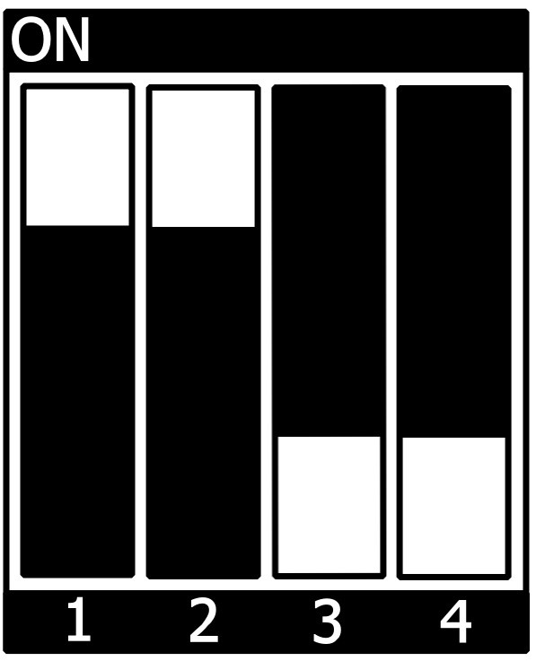
How to Debug a Cortex-M4 Application
Engineering Mode
- To use this mode, first check that:
- your board is correctly connected to the host PC with the JTAG
- the boot mode is set correctly on your board to Engineering mode (with S7 DIP switch on phyBOARD-Sargas)
- the application to debug contains some code that configures the system clock in case the Engineering mode is detected (the examples/applications given in the STM32CubeMP1 contain this code, so you can use it as a reference).
- To start debugging:
- on the left Project Explorer section, click on your Project and launch the Debug Configurationmenu with Run → Debug as → STM32 Cortex-M C/C++ Application
- in the Debug Configuration menu, go to Debugger tab, select the option thru JTGA/SWD link (Engineering mode)
- if you are using an ST-LINK, you do not have to change more options
- click on Debug
Debug configuration setting for Engineering mode:

Production Mode
- To use this mode, first check that:
- your board is correctly connected to the host PC with:
- a JTAG (ST-LINK or SEGGER J-LINK)
- a Network connection: USB OTG (Ethernet point to point) or Ethernet (IP address attributed by DHCP server or to be manually configured)
- a Serial Link (to access the Linux remote console).
- your board is powered on and Linux is booted and running
- the application to debug contains some code that configures the system clock in case the Engineering mode is detected (the examples/applications given in the STM32CubeMP1 contains this code, so you can use it as a reference).
- your board is correctly connected to the host PC with:
Tip
With the phyBOARD-Sargas, to create the network connection, the easiest way is it to use the USB OTG (connector X12) as it is already configured with a fixed IP adress 192.168.7.1 (see Create an SSH Connection with USB OTG or Ethernet)
- To start debugging:
- on the left Project Explorer section, click on your Project and launch the Debug Configurationmenu with Run → Debug as → STM32 Cortex-M C/C++ Application
- in the Debug Configuration menu, go to Debugger tab, keep the default option which is: thru Linux Core (Production mode)
- In the Connection section select the Serial Port (ex: MPU Serial (/dev/ttyUSB0)) and the Ethernet address of your target (ex: 192.168.7.1)
- click on Debug
Debug configuration setting for production mode:

At debug launch, the following pop-up will appear:
- a message requesting the SSH Password => User ID = "root" / no password (you can check the box "save the password", so it will not be asked again)
- a Warning message: The RSA key has to be approved => click on "Yes"
- a Progress bar information that informs about the firmware loading progress into the target
- a message "Confirm Perspective switch" => click on "Switch" (you can check "remember my decision, so it will not be asked again)
When debug mode is ready, the following logs will appear in red in the console, with some information from the debugger:
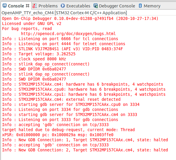
Below are the 3 steps which are done to enter the Debug session in Production mode:
1. The firmware-built binary is transferred to the target through the network link (ssh protocol). It is copied in the Cortex-A Linux file system.
2. The firmware is loaded to Cortex-M core thanks to the “remoteproc” framework.
3. The Debug session is started via JTAG/SWD connection.
Basic commands to debug an application:
- Set breakpoints to desired lines → Make sure that "Skip all breakpoints" button is not active

- Start program and debugging with "Resume" button

- Stop debug session with "Terminate" button

STM32MP15x Low Power Modes
Low Power Overview
https://wiki.st.com/stm32mpu/wiki/Power_overview
How to Define Your Low Power Strategy
https://wiki.st.com/stm32mpu/wiki/How_to_define_your_low-power_strategy
Revision History
| Version | Changes | Date |
|---|---|---|
| L-876e.A0 | Preliminary Edition | 11.09.2020 |
| L-876e.A1 | Update for PD21.1.0 | 02.03.2021 |
| L-876e.A2 | Update for PD21.2.0 Introducing Device Tree Overlay add phyCAM-P VM-010 and RS485 add-ons | 12.10.2021 |
| L-876e.A3 | Update for PD21.2.1:
$5.4 Choose a BSP Image to be Build and Deployed $5.5 Get and Initialize the BSP Environment
$12.2 Build yocto machine from generated Device Tree | 13.12.2021 |