Gesamtbetrag:
zzgl. Mwst.
Application Guide - Using the ISPs on the phyBOARD-Pollux i.MX 8M Plus (L-1036e.A0)
Table of Contents
Introduction
This document describes the functions and configuration options of the ISP (Image Signal Processor) of the i.MX 8M Plus. An ISP provides various image optimization functions that are performed independently of the processing unit (CPU) and so do not burden the limited system resources. Furthermore, the use of an ISP accelerates software development, since the associated algorithms do not have to be elaborately implemented and can therefore be started immediately with the verification.
Requirements
Before you start with this document, please read the current Getting Started Manual L-1029e.A1. There you will find a basic description of how to connect the camera, configure the operating system, and take a picture with the camera.
Video Devices and Sub-devices
Access to the ISP and with it to the images captured via the ISP is done classically via a V4L2 Video Device. The following video devices are available for access:
/dev/video-csi1        # Port CSI1
/dev/video-csi2        # Port CSI2
Furthermore, V4L2 sub-devices are available to access the connected sensors. For the supported PHYTEC phyCAMs VM-x16 and VM-x17, the following sub-devices are created via udev rules:
/dev/cam-csi1          # Sensor am Port CSI1
/dev/cam-csi2          # Sensor am Port CSI2
Configuring the ISPs
Background
The ISP is configured using various configuration files in XML and JSON format. The setting of these configurations is done by the isp_media_server Daemon, which is located in the BSP under /opt/imx8-isp/bin/. This daemon must be active in the background to use the ISP. The isp_media_server works with two configuration files, Sensor0_Entry.cfg and Sensor1_Entry.cfg, where Sensor0_Entry.cfg is responsible for the CSI1 port and Sensor1_Entry.cfg for the CSI2 port. Both files must be in the same path as the isp_media_server Daemon, otherwise they cannot be loaded.
Information
In the PHYTEC BSP, the isp_media_server is automatically started via the imx8-phycam-isp.servicesystemd service. A wrapper script (see PHYTEC phyCAM - Board-Level Cameras) handles the automatic configuration for the supported PHYTEC phyCAMs VM-x16 and VM-x17.
The following describes how to start the isp_media_server manually. However, for the supported PHYTEC phyCAMS VM-x16 and VM-x17, this is usually not necessary.
Note
In order to start the isp_media_server, the imx8-phycam-isp.servicesystemd service must be stopped first.
target# systemctl stop imx8-phycam-isp.service
The isp_media_server Daemon requires a transfer parameter at startup that specifies which CSI ports are used.
target# ./isp_media_server CAMERA0        # CSI1
target# ./isp_media_server CAMERA1        # CSI2
target# ./isp_media_server DUAL_CAMERA    # Both CSI1 and CSI2
Sensor Configuration Files (Sensor0_Entry.cfg & Sensor1_Entry.cfg)
Besides a reference to the used userspace driver, the sensor configuration files also contain the supported modes and the selection of the active mode. Each mode contains a reference to a configuration file for the ISP (xml) and the Dewarp engine (dwe). The paths given are relative to the path of the sensor configuration files.
Sensor0_Entry.cfg Beispiel
name="phycam"
drv = "phycam.drv"
mode= 1

[mode.0]
xml = "xml/VM-017-COL_AO062-C_1280x720.xml"
dwe = "dwe/VM-017_AO062_1280x720.json"

[mode.1]
xml = "xml/VM-017-COL_AO062-C_1920x1080.xml"
dwe = "dwe/VM-017_AO062_1920x1080.json"

[mode.2]
xml = "xml/VM-017-COL_AO062-C_2592x1944.xml"
dwe = "dwe/VM-017_AO062_2592x1944.json"
Note
Each mode defined here must be supported in the kernel driver of the sensor used. It is not possible to add new modes without adapting the kernel driver.
Note
The sensor configuration files are read in when the corresponding video device is accessed and buffered until images have been fetched from the sensor. The configuration can therefore be adjusted for each streaming operation without having to restart the isp_media_server Daemon.
PHYTEC phyCAM - Board-Level Cameras
For the supported PHYTEC board-level cameras phyCAM VM-x16 and VM-x17, there are ready-made sensor configuration files (see Pre-calibrated Configurations).
A wrapper script for the isp_media_server Daemon automatically detects which CSI port is used and which sensors are connected and selects the appropriate sensor configuration file. The selection is done via a link instead of Sensor0_Entry.cfg bzw. Sensor1_Entry.cfg, which points to the matching configuration file.
This means that changes to Sensor0_Entry.cfg or Sensor1_Entry.cfg directly affect the linked configuration files and thus, for example, to change the mode, only the Sensor0_Entry.cfg or Sensor1_Entry.cfg files need to be adjusted.
Mode Selection
In order to select one of the available modes, it must simply be set in the corresponding sensor configuration file. Please note that there must be a space between '=' and mode.
Sensor0_Entry.cfg, active mode = 1
name="phycam"
drv = "phycam.drv"
mode= 1

[mode.0]
xml = "xml/VM-017-COL_AO062-C_1280x720.xml"
dwe = "dwe/VM-017_AO062_1280x720.json"

[mode.1]
xml = "xml/VM-017-COL_AO062-C_1920x1080.xml"
dwe = "dwe/VM-017_AO062_1920x1080.json"

[mode.2]
xml = "xml/VM-017-COL_AO062-C_2592x1944.xml"
dwe = "dwe/VM-017_AO062_2592x1944.json"
Sensor0_Entry.cfg, active mode = 0
name="phycam"
drv = "phycam.drv"
mode= 0

[mode.0]
xml = "xml/VM-017-COL_AO062-C_1280x720.xml"
dwe = "dwe/VM-017_AO062_1280x720.json"

[mode.1]
xml = "xml/VM-017-COL_AO062-C_1920x1080.xml"
dwe = "dwe/VM-017_AO062_1920x1080.json"

[mode.2]
xml = "xml/VM-017-COL_AO062-C_2592x1944.xml"
dwe = "dwe/VM-017_AO062_2592x1944.json"
Lens Selection
Calibration data is already available for some lenses from the PHYTEC range. In combination with the phyCAM camera modules, you can directly start the evaluation of functions like Dewarping or Lens Shade Correction. To select one of the pre-calibrated lenses you only have to set the lens for AR0144 (VM-x16) or AR0521 (VM-x17) in the run_isp.sh wrapper script. The wrapper script is located in /opt/imx8-isp/bin/ as are the sensor configuration files.
The following lenses are currently supported:
| Camera | Objective | Note |
|---|---|---|
| VM-x16 | AO082 | default |
| VM-x16 | AO086 | |
| VM-x17 | AO062 | default |
| VM-x17 | AO070.A1 |
PHYTEC marks objectives with an integrated IR filter with the suffix -C (see Pre-calibrated Configurations). Within the BSP, the selection whether with or without an IR filter is made automatically based on the camera used. If the AO086 is entered in the run_isp.sh, the ISP is automatically configured to match an AO086-C for a color variant of the VM-x16. For a monochrome variant of the VM-x16, the configuration for an AO086 is used.
run_isp.sh - Default Objective
#!/bin/bash

AR0144_LENS="AO082"
AR0521_LENS="AO062"

if ! [ -e /dev/cam-csi1 ] && ! [ -e /dev/cam-csi2 ]; then
        echo "No camera"
        exit 6
fi
[...]
run_isp.sh - Alternative Objective
 !/bin/bash

AR0144_LENS="AO086"
AR0521_LENS="AO070.A1"

if ! [ -e /dev/cam-csi1 ] && ! [ -e /dev/cam-csi2 ]; then
        echo "No camera"
        exit 6
fi
[...]
VVEXT-Tool
The VVEXT tool is part of the Board Support Package (BSP) and can be used to manually configure the ISP during live image output. It offers a comprehensive possibility to test the functions of the ISP and, if necessary, to transfer settings to the XML file afterward.
Note
Changes made with the VVEXT tool are only valid for the current streaming process. With each new streaming process, the configuration is taken over again from the sensor configuration files. Persistent changes must be entered in the configuration files.
The VVEXT tool is located at: /opt/imx8-isp/bin/
The tool is started using:
target# ./vvext 0
The passing parameter represents the video device used (0 = /dev/video0 , 1 = /dev/video1 , etc.).
The order of the standard video devices (/dev/video0, /dev/video0, etc.) does not necessarily have to correspond to the order of the video devices described above. The assignment of the PHYTEC-specific video devices (/dev/video-csi1 and /dev/video-csi2) to the standard video devices can be easily found out with the following command:
target# ls -l /dev/video-csi*
lrwxrwxrwx    1 root     root             6 Jul 12 05:41 /dev/video-csi1 -> video0
V4L2 External Control Interface
The VVEXT tool uses the viv_ext_ctrl V4L2 control internally to access the ISP. This mechanism can also be used externally and independently of the VVEXT tool to change the configuration of the ISP at runtime. On the NXP website, you can find the documentation for the viv_ext_ctrl V4L2 control and the available parameters under the following link: IMX8MPISPUV4L2IUG.pdf (User account/login to NXP website required)
The BSP contains an exemplary implementation in the form of a Python demo. The demo can be found under /root/gstreamer-examples/isp_gstreamer-examples/gst-python_demo/isp-demo-cam.py
Pre-calibrated Configurations
The BSP PD22.1.0 supports per se the following board-level cameras and the following optics. For more information about the board-level cameras and available lenses, please refer to our homepage or contact our FAE team.
| Board Level Camera | Objective | Resolution | XML | JSON (for DeWarp/Lens Equalization) |
|---|---|---|---|---|
| VM-_16-BW-M/-L | AO082 (12 mm) | 1280x800 | VM-016-BW_AO082_1280x800.xml | VM-016_AO082_1280x800.json |
| VM-_16-BW-M/-L | AO082 (12 mm) | 1280x720 | VM-016-BW_AO082_1280x720.xml | VM-016_AO082_1280x720.json |
| VM-_16-COL-M/-L | AO082-C (12 mm) | 1280x800 | VM-016-COL_AO082-C_1280x800.xml | VM-016_AO082_1280x800.json |
| VM-_16-COL-M/-L | AO082-C (12 mm) | 1280x720 | VM-016-COL_AO082-C_1280x720.xml | VM-016_AO082_1280x720.json |
| VM-_16-BW-M/-L | AO086 (1.8 mm) | 1280x800 | VM-016-BW_AO086_1280x800.xml | VM-016_AO086_1280x800.json |
| VM-_16-BW-M/-L | AO086 (1.8 mm) | 1280x720 | VM-016-BW_AO086_1280x720.xml | VM-016_AO086_1280x720.json |
| VM-_16-COL-M/-L | AO086-C (1.8 mm) | 1280x800 | VM-016-COL_AO086-C_1280x800.xml | VM-016_AO086_1280x800.json |
| VM-_16-COL-M/-L | AO086-C (1.8 mm) | 1280x720 | VM-016-COL_AO086-C_1280x720.xml | VM-016_AO086_1280x720.json |
| VM-_17-BW-M/-L | AO062 (12 mm) | 2592x1944 | VM-017-BW_AO062_2592x1944.xml | VM-017_AO062_2592x1944.json |
| VM-_17-BW-M/-L | AO062 (12 mm) | 1920x1080 | VM-017-BW_AO062_1920x1080.xml | VM-017_AO062_1920x1080.json |
| VM-_17-BW-M/-L | AO062 (12 mm) | 1280x720 | VM-017-BW_AO062_1280x720.xml | VM-017_AO062_1280x720.json |
| VM-_17-COL-M/-L | AO062-C (12 mm) | 2592x1944 | VM-017-COL_AO062-C_2592x1944.xml | VM-017_AO062_2592x1944.json |
| VM-_17-COL-M/-L | AO062-C (12 mm) | 1920x1080 | VM-017-COL_AO062-C_1920x1080.xml | VM-017_AO062_1920x1080.json |
| VM-_17-COL-M/-L | AO062-C (12 mm) | 1280x720 | VM-017-COL_AO062-C_1280x720.xml | VM-017_AO062_1280x720.json |
| VM-_17-BW-M/-L | AO070.A1 (2.4 mm) | 2592x1944 | VM-017-BW_AO070.A1_2592x1944.xml | VM-017_AO070.A1_2592x1944.json |
| VM-_17-BW-M/-L | AO070.A1 (2.4 mm) | 1920x1080 | VM-017-BW_AO070.A1_1920x1080.xml | VM-017_AO070.A1_1920x1080.json |
| VM-_17-BW-M/-L | AO070.A1 (2.4 mm) | 1280x720 | VM-017-BW_AO070.A1_1280x720.xml | VM-017_AO070.A1_1280x720.json |
| VM-_17-COL-M/-L | AO070.A1-C (2.4 mm) | 2592x1944 | VM-017-COL_AO070-C.A1_2592x1944.xml | VM-017_AO070.A1_2592x1944.json |
| VM-_17-COL-M/-L | AO070.A1-C (2.4 mm) | 1920x1080 | VM-017-COL_AO070-C.A1_1920x1080.xml | VM-017_AO070.A1_1920x1080.json |
| VM-_17-COL-M/-L | AO070.A1-C (2.4 mm) | 1280x720 | VM-017-COL_AO070-C.A1_1280x720.xml | VM-017_AO070.A1_1280x720.json |
BSP PD22.1.0 Supported Cameras And Optics
ISP Functions Overview
This chapter provides a brief overview of the available functions of the ISP. Not all functions have been verified by PHYTEC or are included in the pre-calibrated configurations.
If there is a need for functions that have not been verified, please contact PHYTEC support.
| Feature/Camera-Module | VM-_16-COL | VM-_16-BW | VM-_17-COL | VM-_17-BW |
|---|---|---|---|---|
Color Processing (Brightness/Contrast/Saturation/Hue) (CPROC) | ||||
De-Noise Prefilter (DPF) | ||||
Chromatic Aberration Compensation (CAC) | ||||
| not used | |
| fully supported | |
| pre-calibrated | |
| not verified |
ISP Functions
Pre-calibration / Calibration Service
For the application of most of these functions, a calibration of the ISP to the specific optical system (consisting of a camera, lens, and possibly other optical parameters) is required. Depending on the function and application, a basic calibration of the camera module used is already sufficient. For selected phyCAM modules, this is already included in the BSP of the phyCORE processor module.
PHYTEC offers an individual calibration service for your application so that you can benefit optimally from the ISP functions of the i.MX 8M Plus in your application. As a result, you will receive calibration files (XML/JSON) for the phyCORE-i.MX 8M Plus BSP for your specific combination of board-level camera, lens, and application parameters that will make the desired ISP functions usable in your application.
If parameters of the optics have to be considered as well, an individual calibration of the complete system is necessary. This can be used, for example, to calibrate image rectification for wide-angle / fisheye lenses or to compensate for edge loss of image brightness.
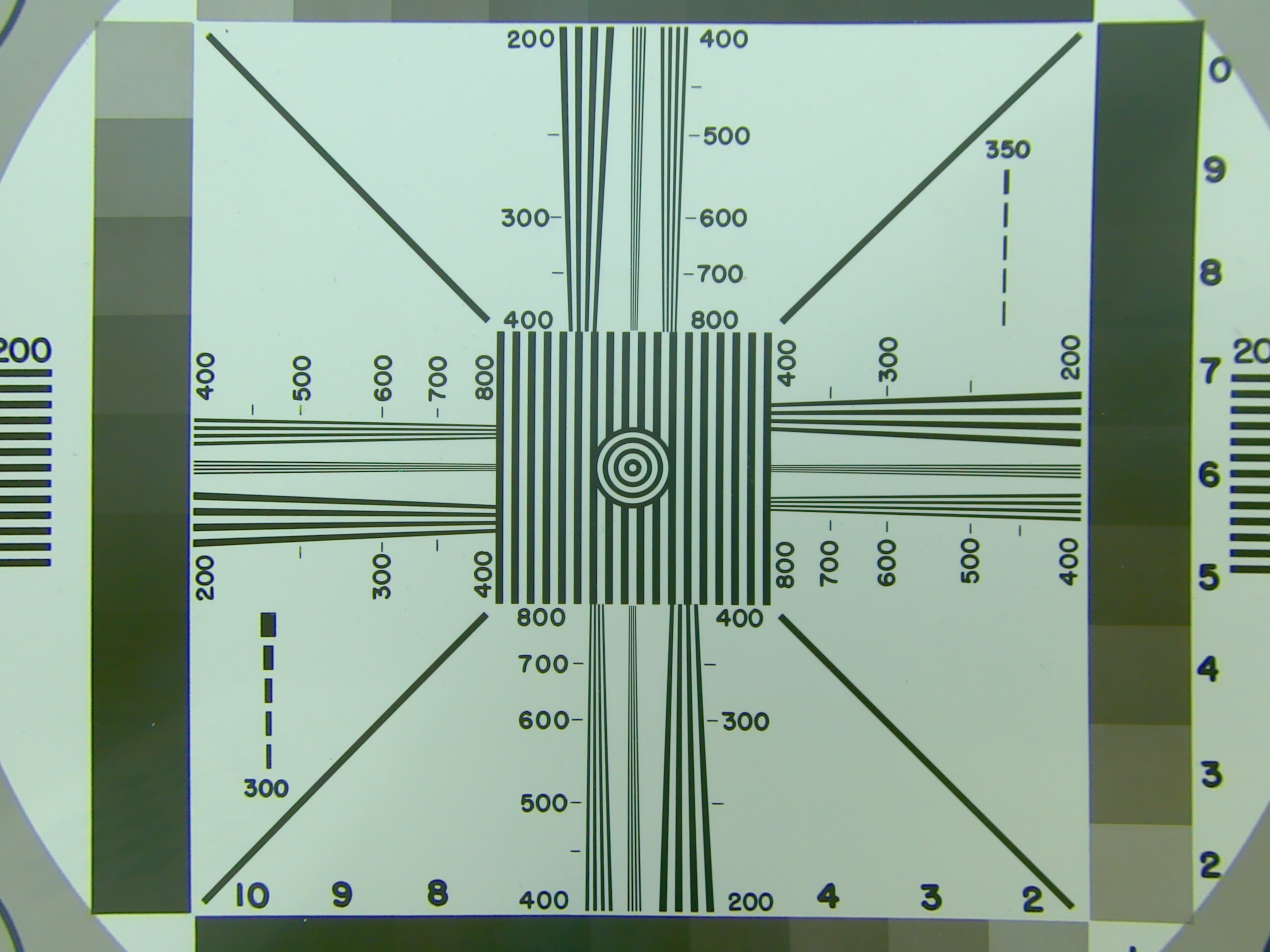
An individual calibration is performed in our laboratory on the basis of the intended system components and your specifications of the optical parameters of your application. For example, reference charts are recorded with the planned camera system and the calibration data for the ISP is calculated on the basis of these measurements.
For more information about the PHYTEC calibration service, please visit our website at Embedded Vision Services.
ISP Function Details
In this section, you will find detailed information about the individual ISP functions, and the respective direct reference to the configuration is shown.
Demosaicing
In order to be able to convert the Bayer pattern of the image sensors into the RGB or YUV color space, the so-called demosaicing or DeBayering is used. This can be done either completely in software (i.e. using the NEON coprocessors or the GPU), but ideally using the ISP.
Different methods can be used for demosaicing. PHYTEC does not have information on which method(s) are used by the ISP of the i.MX 8M Plus.
Configuration Options
switch mode / Enable
Demosaicing can be deactivated (bypassed) using switch mode. This is necessary for monochrome board-level cameras (grayscale cameras).
It should be noted that any color corrections are still performed. Which leads to erroneous gray values. In addition to deactivating demosaicing, Automatic White Balance (AWB) should also be deactivated. Instructions for deactivating can be found in AWB.
Threshold for Demosaicing Texture Detection
Threshold sets the demosaicing texture detection. Here "0" stands for maximum edge sensitivity. "255" uses no detection.
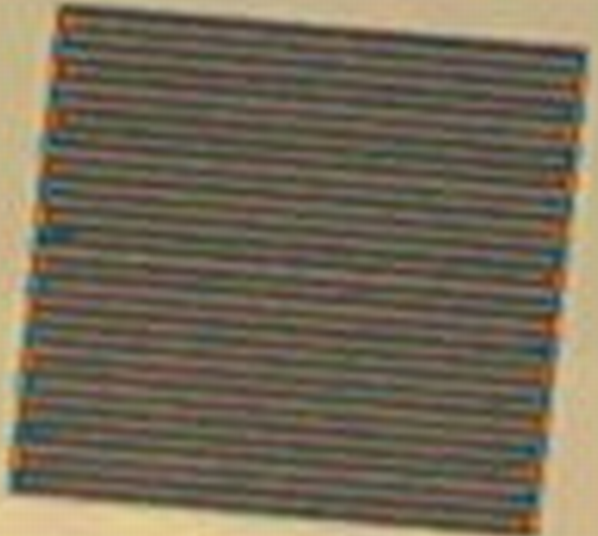

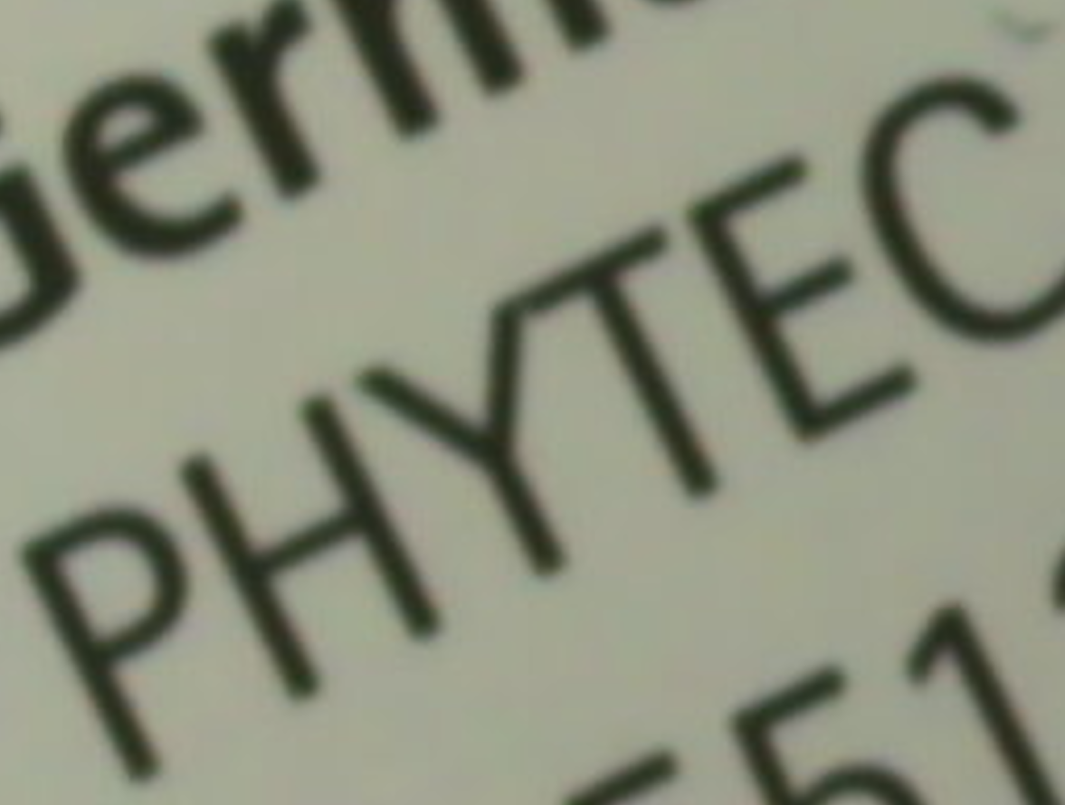
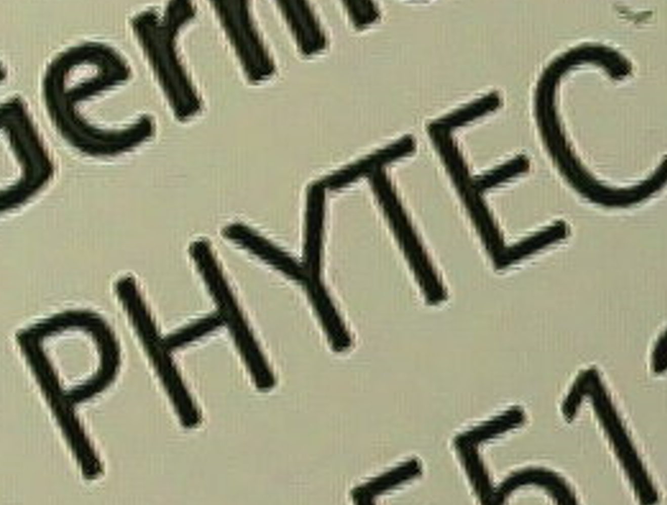
Demosaicing Texture Detection (Threshold=0)
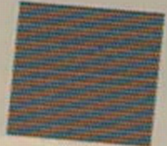

Demosaicing Texture Detection (Threshold=255)
The advantage of high sensitivity is, for example, that straight edges are displayed more cleanly. The moiré effect can be reduced as a result. A disadvantage is, among other things, that fine not straight structures become less clear.
Both can be seen well in the example images.
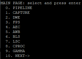
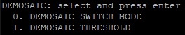
VVEXT
Select DEMOSAIC to enter the corresponding menu.
XML
The demosaicing configuration is done under the <tuning> element within the XML:
<tuning>

...

        <demosaic enable="false">
            <threshold>0</threshold>
        </demosaic>

...

</tuning>
Filter Functions (Sharpening, Noise Reduction)
The sharpening algorithm increases the contrast at the edges of a structure. Sharpening at too high a level can lead to "halo" effects. This is a bright glow at the edges. Furthermore, fine structures can become visible that should actually be suppressed.
Noise reduction (denoise) usually uses Gaussian, box-blur, or median filters. The method used by ISP of the i.MX 8M plus is not known to us. In general, noise reduction results in a kind of soft focus. The image loses details as a result.
Therefore, a compromise between noise reduction and sharpness should always be sought.
Configuration Options
On/Off
Turns the function on or off.
Denoise Level
The noise reduction level can be set between 1 to 10.

Denoise Level 10
Sharpen Level
The strength of the sharpening can be set in steps from 1 to 10.

Sharpen Level 10


Sharpen Level 5 and Denose Level 3
VVEXT

XML
The filter configuration is done under the <tuning> element within the XML:
<tuning>

...

       <filter enable="true" auto="true">
                 <denoise>3</denoise>
                 <sharpen>4</sharpen>
        </filter>

...

</tuning>
Color Processing (CPROC)
CPROC provides the features for brightness, hue, saturation, and contrast.
- Brightness increases or decreases the RGB values evenly.
- By means of the hue (Hue) the color space gamut is run through.
- Saturation, also called color intensity, describes how far the hue stands out from the black/white plane (0=monochrome).
- Contrast makes dark areas darker and light areas lighter or vice versa. This creates a higher or lower difference between the areas and the contrast ratio increases or decreases.
The CPROC operates with the BT.601 mode. This has a value range of <16 ... 235>. Deactivating the BT.601 color profile is currently not possible.
BT.601 defines how digital interlaced video signals are to be encoded. Since the ISP uses YUV 4:2:2 and this is based on BT.601, this standard is used even if the actual picture is not interlaced.
Configuration Options
On/Off
Turns the function on or off.
Brightness
Value range: <-127 ... 127>
Contrast
Value range: <0 ... 1.99>
Saturation
Value range: <0 ... 1.99>
Hue
Value range: <-127 ... 127>
VVEXT

XML
Configuration by the user is not possible.
The adjustments can be made by PHYTEC. Please contact our support for this purpose.
Blacklevel Compensation (BLS)
Image sensors often work internally with an offset in order to be able to carry out any corrections already in the sensor. Only with an offset is it possible to allow corrections that would theoretically result below the minimum level. After the corrections, the offset that is not needed can be subtracted again. If this is not done, the sensor will not reach the absolute black value.
Depending on the sensor type or its configuration, this offset can vary greatly.
For the configurations of the board-level camera VM-017, no compensation is needed at the current state. The VM-016 models, on the other hand, are reduced by 160 (12 bits). (PD22.1.0)
Configuration Options
On/Off (Bypass)
Turns the function on or off.
Correction Values of the Individual Color Channels
Value range: <0 ... 4095>
The color channels can be corrected separately from each other.
VVEXT
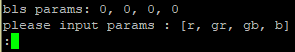
Note
Bypass is not available within the VVEXT tool. As a substitute, a setting of the adjustment to "0, 0, 0" can be used.
XML
The BLS configuration can be done under the <tuning> element within the XML:
<tuning>

...

      <bls bypass="true">
         <red>0</red>
         <green.b>0</green.b>
         <green.r>0</green.r>
         <blue>0</blue>
      </bls>

...

</tuning>
Automatic Exposure Control (AEC)
The AEC adjusts the brightness of the image to a target range by variation of the exposure time and the gain value.
If the AEC is switched off, the gain and exposure time of the camera sensor can be selected manually.
The AEC directly affects the registers of the board-level camera and configures the required analog gain and exposure time in the sensor.
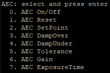
Configuration Options
On/Off
Turns the function on or off.
Reset
Resets the AEC unit so that it rebalances.
SetPoint
Value range: <0 ... 255>
The average brightness value of the image should be reached as a target value.
DampOver
Value range: <0 ... 1>
Prerequisite: DampOver <= DampUnder
The damping factor specifies how fast the regulation is to be. The larger the value, the slower the AEC response.
DampUnder
Value range: <0 ... 1>
Prerequisite: DampUnder >= DampOver
The larger the value, the slower the AEC regulates.
Tolerance
Value range: <0 ... 100>
Tolerance on the set point (+/-), from which the control corrects.
Small tolerances lead to faster readjustment but can cause the regulator to oscillate. Large tolerances can lead to spurious control.
Gain
Value range: Permissible gain of the camera module used.
Can only be used with AEC deactivated. The gain is configured directly within the image sensor (analog signal amplification).
ExposureTime
Value range: Within the allowed exposure time range of the camera module used.
Can only be used with AEC deactivated.
The control range of the Exposure Time is basically determined by the setting of the camera.
If a longer exposure time is desired, the horizontal_blankings or vertical_blankings of the camera must be increased.
This can be configured using v4l2-ctls.
If the vertical and horizontal blankings are greatly increased, the exposure time may be miscalculated. It is recommended to always use only one of the values and leave the default value of the other.
Flicker Avoidance Period
The ISP offers the feature of flicker suppression. The flicker suppression aims at the suppression of brightness fluctuations of the image, which are caused by differences in the frequencies of the light source (e.g. fluorescent lamps, LEDs) and the image acquisition frequency (beatings).
This feature has not yet been put into operation by PHYTEC and is therefore not supported for the time being.
VVEXT
XML
The AEC configuration can be done under the <tuning> element within the XML:
<tuning>

...

      <ae enable="true" bypass="false">
         <afps>false</afps>
         <flicker.period>1</flicker.period>
         <set.point>100</set.point>
         <damping.over>0.2</damping.over>
         <damping.under>0.8</damping.under>
         <tolerance>15</tolerance>
      </ae>

...

</tuning
Exposure Control (EC)
By means of the EC, the analog gain and the exposure time of the sensor can be set manually.
Configuration Options
Gain
Value range: Permissible gain of the camera module used.
Can only be used with AEC deactivated. The gain is configured directly within the image sensor (analog gain).
ExposureTime
Value range: Allowed exposure time of the board-level camera used.
Can only be used with AEC deactivated. The control range of the Exposure Time is basically determined by the setting of the camera.
If a longer exposure time is desired, the horizontal_blankings or vertical_blankings of the camera must be increased.
This can be configured e.g. using v4l2-ctls.
Note
If the vertical and horizontal blankings are greatly increased, the exposure time may be miscalculated.
This miscalculation cannot be corrected by PHYTEC, since we do not have the associated information on the internal operations.
It is recommended to always use only one of the values and to leave the default value of the other.
VVEXT
Within the VVEXT tool, the configuration of the EC can be done via the feature of the AEC.
XML
The EC configuration can be done under the <tuning> element within the XML:
<tuning>

...

               <ec>
                   <gain>2.00</gain>
                   <intergration.time>0.002</intergration.time>
               </ec>

...

</tuning>
White Balance (WB)
Instead of the AWB, the white balance can also be performed manually.
Here, the individual color values can be set separately.
Note
It is recommended to always disable the LSC as well when disabling the AWB. According to previous experience, this leads to correct image output.
If the LSC is to remain active, further adjustments must be made in the XML file, as with the pre-calibrated XML files of the monochrome camera modules (correction values for color correction and the AWB).
The AWB should remain activated and be set to Mode 1.
For further information please contact PHYTEC Support.
The individual channels cannot be set via the VVEXT tool. An adjustment in the XML is necessary.
Configuration Options
Color Channel Gains
Value range: <0 ... 3.999>
The color channels are manipulated within the ISP.
Color Correction Offsets
Value range: <-2048 ... 2047>
An offset is added within the ISP.
Color Correction Matrix
The color correction matrix is determined during the calibration process. So that this does not influence the manual white balance, the identity matrix is selected.
XML
The WB configuration can be done under the <tuning> element within the XML:
<tuning>

...

       <wb>
            <cc.matrix>[1,0,0,0,1,0,0,0,1]</cc.matrix>
            <cc.offset>
                <blue>0</blue>
                <green>0</green>
                <red>0</red>
            </cc.offset>
            <wb.gains>
                <blue>1.0</blue>
                <green.b>1.0</green.b>
                <green.r>1.0</green.r>
                <red>1.0</red>
            </wb.gains>
        </wb>

...

</tuning>
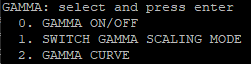
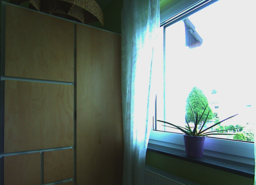
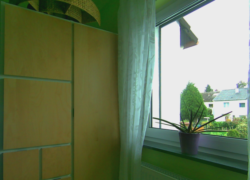
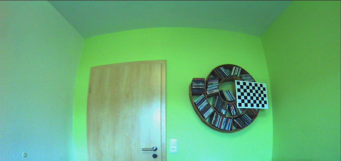
Gamma Correction (GC)
Since the eye's perception of brightness is not linear, but image sensors usually work linearly, an adjustment can be made by means of gamma correction. The value to be set depends on the sensor, the color space used, and the display.
Gamma correction converts the image data non-linearly using a power function. Here, the brightest and darkest values remain relatively unaffected. Accordingly, the middle values are manipulated particularly strongly.
Configuration Options
On/Off
Turns the function on or off.
Note
By default, the GC works with a correction curve that corresponds approximately to the factor of 2.2 for logarithmic segmentation.
Gamma Scaling Mode
Logarithmic (LOG) segmentation or linear (Equidistante (EQU)) segmentation can be used. A logarithmic segmentation results in a higher contrast ratio but can increase color banding (hard color gradients).
Gamma Curve
Value range: <0.1 ... 4.0>
The exponent of the power function can be set here.
Note
The gamma settings within the XML are transferred by means of a coded string. Adjustments can be made by PHYTEC.
Please contact PHYTEC support for more information.
VVEXT
XML
The GC configuration can be done under the <tuning> element within the XML.
<tuning>

...

       <gc enable="false"/>

...

</tuning>
Defect Pixel Cluster Correction (DPCC)
Image optimization can be performed by means of cluster detection or correction of defective clusters.
The correction works dynamically, so that individual clusters may be sporadically recognizable depending on the lighting conditions.


Without (left) and with (right) Defect Pixel Cluster Correction
Even if the sensor used employs an internal correction, it may be possible to achieve a better result together with the ISP. This should be tested individually.
Configuration Options
On/Off
Turns the function on or off.
VVEXT
![]()
XML
The DPCC configuration can be done under the <tuning> element within the XML:
<tuning>

...

      <dpcc enable="true"/>

...

</tuning>
Wide Dynamic Range 3 (WDR3)
The following is a shot without and with WDR3:
Without (left) and with (right) Wide Dynamic Range 3
WDR3 carries out tone mapping. There are various procedures for this. NXP does not describe which one is used exactly.
The ISP provides WDR3 V1 and V3. V1 is the Global Wide Dynamic Range and V3 the WDR3.
Configuration Options
On/Off
Turns the function on or off.
Auto
The auto function has not been put into operation.
Strength (strength)
Value range: <0...128> / Default=16
Maximum Gain (maxGain)
Value range: <0...128> / Default=100
Global Strength (globalStrength)
Value range: <0...128> / Default=100
VVEXT

XML
The WDR3 configuration can be done under the <tuning> element within the XML:
<tuning>

...

      <wdr>
         <v1 enable="false" auto="false">
         </v1>
         <v3 enable="true" auto="false">

                <gain.max>16</gain.max>
                <strength>100</strength>
                <strength.global>100</strength.global>
         </v3>
      </wdr>

...

</tuning>
DeWarp (DWE)
Lens distortion is corrected by the DeWarp Engine.
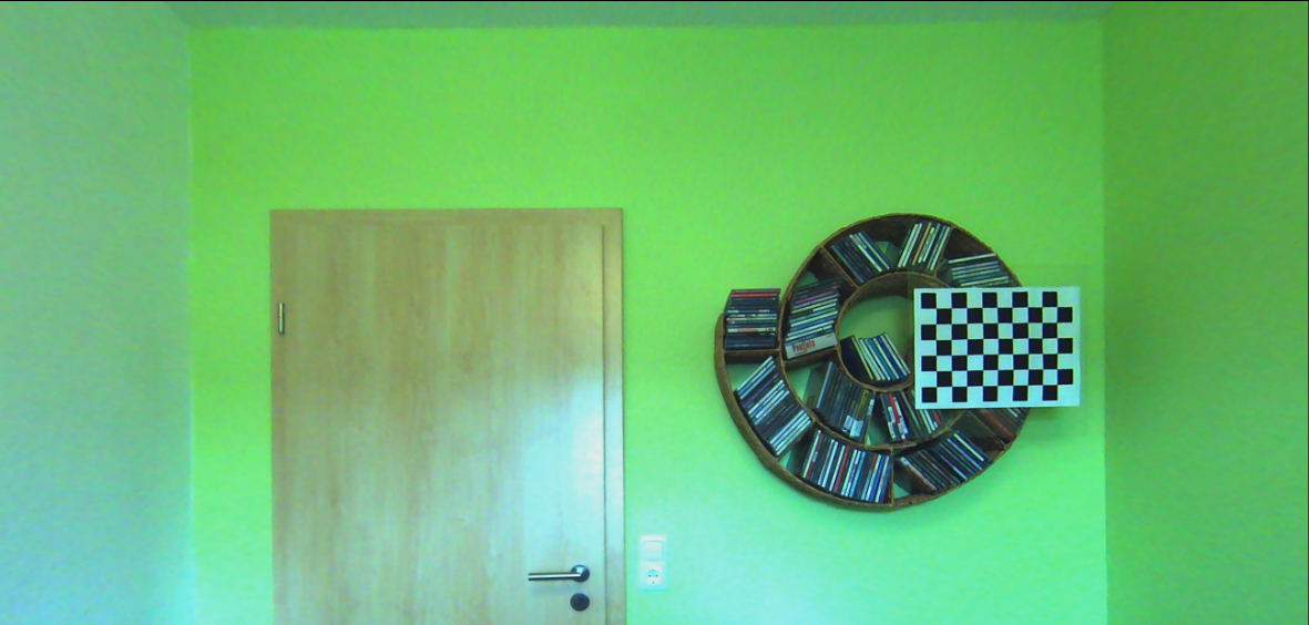
Without (left) and with (right) DeWarp
It should be noted that de-warping always results in the loss of image content (at the edges). The following images were created with and without de-warping. It is easy to see that a good part of the image has been removed.

Without (left) and with (right) DeWarp (cropped image)
The cause is illustrated by the following image (rectification using a photo editing tool):
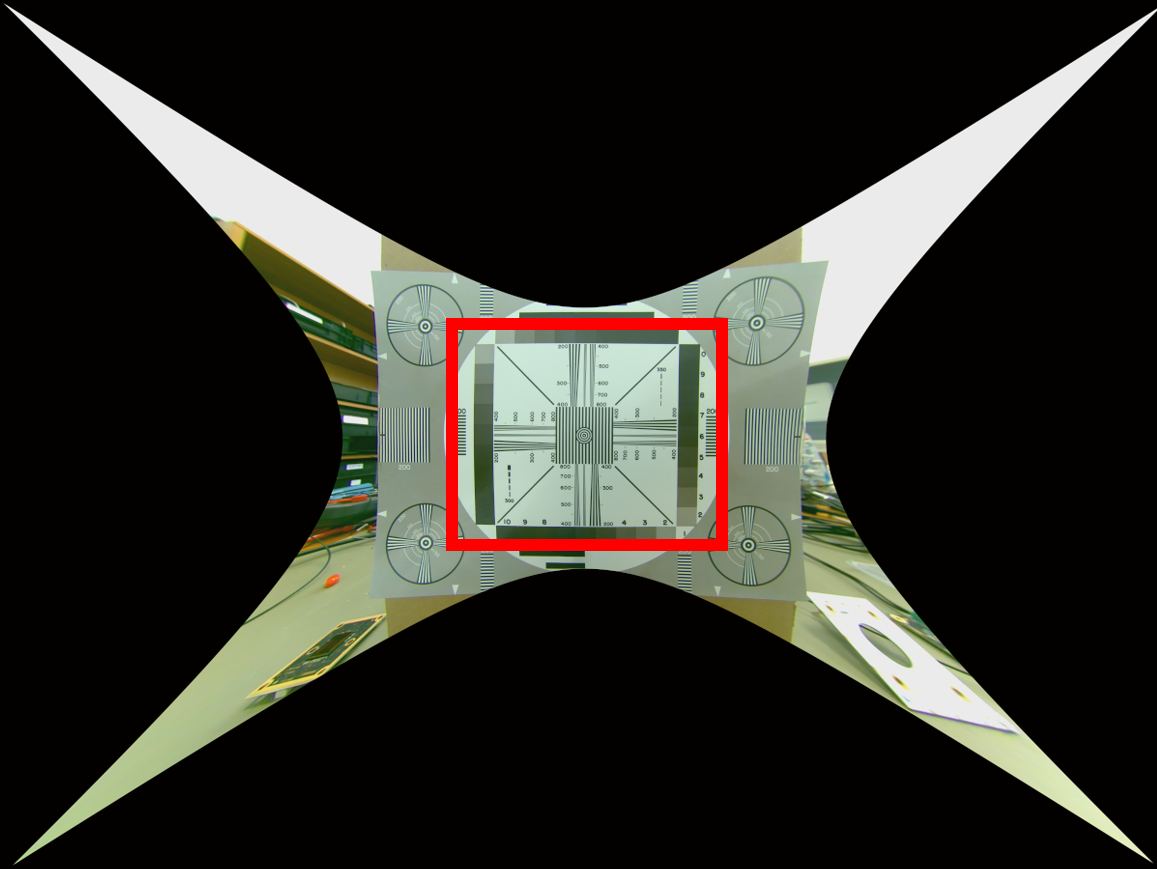
DeWarp Mode of Operation
As you can see, the image has to be stretched considerably at the corners. This results in areas with no content. In addition, rectification is not constant everywhere. As a result, it is not possible to display a completely rectified image.
When calibrating the de-warping unit, it is not possible to define the exact size of the image that will be displayed later. It can be assumed that the DeWarping unit will output a rather too small but therefore better-rectified image.
If you plan to use the DeWarping function, you should take into account when selecting the lens that the captured image section must be larger than the one required by the application.
In principle, the DeWarping unit also offers the features "Split_Screen" and "Fisheye_Expand". Both functions have not been verified by PHYTEC.
Fisheye_Expand, for example, rectifies a circular image in 1:1 format into a rectangular image. We are not aware of any configuration options at this time.
Split_Screen can be used to split the image into several segments. Like Fisheye_Expand, it seems to work only with circular images in 1:1 format. We do not know of any configuration options for this at present.
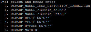
Configuration Options
Only configuration options that PHYTEC has put into operation are discussed here.
On/Off (bypass)
Turns the function on or off.
hflip
The left and right sides of the image are mirrored.
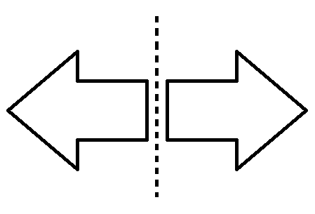
hflip
vflip
The top and bottom sides are mirrored.
![]()
vflip
VVEXT
JSON
In the JSON file, the configurations can be made.
...

            "bypass" : true,
            "hflip"  : false,
            "vflip"  : false,

...
Lens Shade Correction (LSC)
Every lens produces vignetting due to its lens system. This can be significant to a greater or lesser degree depending on the lens. Generally speaking, higher quality lenses will have less vignetting. It is also not dependent on focal length, so fish-eye lenses may have less vignetting than a high focal length lens or low distortion lens.
In order to use the LSC feature, the optical system must be calibrated beforehand. PHYTEC has pre-calibrated systems for this purpose (see Pre-calibrated Configurations). For other optics, we offer an individual calibration service.
Configuration Options
On/Off
Turns the function on or off.
The following images show a homogeneous luminous surface with and without LSC.


Without (left) and with (right) Lens Shade Correction
It is recommended to always deactivate the LSC when the AWB is deactivated. According to previous experience, this leads to a correct image output.
If the LSC is still to remain active, further adjustments must be made in the XML as with the pre-calibrated XML files of the monochrome camera modules (color correction values and the AWB).
The AWB should remain activated and be set to Mode 1.
For more information, please contact PHYTEC Support.
VVEXT
![]()
XML
The LSC configuration can be done under the <tuning> element within the XML:
<tuning>

...

      <lsc enable="true"/>

...

</tuning>
Automatic White Balance (AWB)
The automatic white balance is needed to match the different spectral compositions to one white value during the exposure.
To use the AWB feature, the optical system must be calibrated beforehand. PHYTEC has pre-calibrated systems for this purpose (see Pre-calibrated Configurations). For other optics, we offer individual calibration service.
Configuration Options
On/Off
Turns the function on or off.
The following two figures show one exposure without and one with AWB:
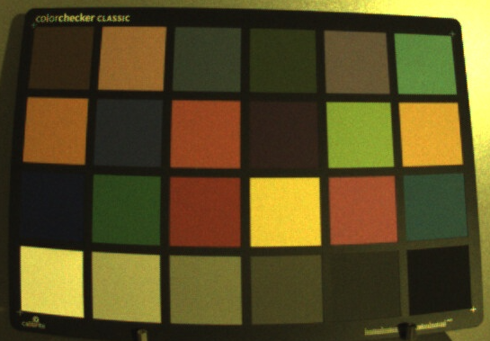
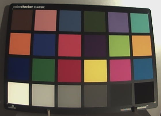
Without (left) and with (right) Automatic White Balance
It should be noted that the initial deactivation of the AWB via the XML file can lead to image errors.
Note
It is recommended to always disable the LSC when disabling the AWB. According to previous experience, this leads to correct image output.
If the LSC is still to remain active, further adjustments must be made in the XML as with the pre-calibrated XML files of the monochrome camera modules (correction values for color correction and the AWB).
The AWB should remain activated and be set to Mode 1.
For more information, please contact PHYTEC Support.
Reset
Performs a reset of the AWB unit, so that it readjusts.
Mode
Mode = 1 stands for manual mode.
Mode = 2 stands for automatic mode.
If the mode is changed during operation, the AWB must be switched off and on again so that the change is accepted.
Profile/Index
The system is calibrated with a certain number of profiles. These profiles can be selected directly without control. Mode 2 must be selected for this purpose.
PHYTEC has used the following profiles for the pre-calibration: 0=A ; 1=D50 ; 2=D65 ; 3=D75 ; 4=F11 (TL84)
Damping
Activating the attenuation makes the white balance a bit more sluggish.
This can make the control appear more inconspicuous to an observer. The attenuation setting should be made according to the requirements of the end application.
VVEXT
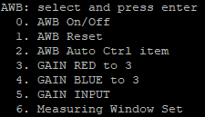
The VVEXT tool offers further configuration options which will not be discussed here.
XML
The VVEXT configuration can be done under the <tuning> element within the XML:.
<tuning>

...

      <awb enable="true">
         <damping>true</damping>
         <index>3</index>
         <mode>2</mode>
      </awb>

...

</tuning>
Denoise Prefilter (DPF)
The Denoise prefilter provides a noise reduction of the camera image. This filter is especially useful during live streaming.
In general, noise reduction results in a kind of blurring. The image loses some contrast as a result.
Without (left) and with (right) Denosie prefilter
Configuration Options
On/Off
Turns the function on or off.
VVEXT
![]()
XML
The DPF configuration can be done under the <tuning> element within the XML:
<tuning>

...

       <dpf enable="true"/>

...

</tuning>
Chromatic Aberration Compensation (CAC)
The effect of chromatic aberration occurs as a color change at the edge of objects. Here, the spectral colors are refracted differently in the lens. This leads to a color error at the focal point.
The higher the contrast at the edge, the more noticeable the discoloration.
PHYTEC has not put the CAC feature into operation. For a correct correction, a calibration is necessary. This function is not available with the pre-calibrated XML files at present.
Configuration Options
On/Off
Turns the function on or off.
VVEXT
![]()
XML
The CAC configuration can be done under the <tuning> element within the XML:
<tuning>

...

      <cac enable="false"/>

...

</tuning>
High Dynamic Range (HDR)
High Dynamic Range refers to the ability of a sensor system to simultaneously reproduce very bright and very dark sections of an image in a clearly recognizable way. This requires certain processes during image acquisition that increase the dynamic range of the image.
To be able to use the feature, an image sensor that supports Digital Overlap (DOL) or Staggered HDR is required. For such sensors, the ISP of the i.MX 8M plus basically provides the required post-processing of the HDR raw data.
In PD22.1.0, the HDR feature is not supported.
Please ask PHYTEC support for more information.
Global Wide Dynamic Range (GWDR)
GWDR is a tone mapping technique that improves the overall brightness gradation.
GWDR has not been verified by PHYTEC. GWDR is not available in the VVEXT tool and is also not prepared in the XML.
We recommend performing optimizations using WDR3. Please ask PHYTEC support for further information.
Automatic Focus Control (AF)
Automatic Focus Control enables the automatic tracking of the image sharpness. The prerequisite for this is a lens that can be adjusted in focus by an electrical signal (or a corresponding parameter). For a given lens, an individual adjustment is required.
The Auto Focus feature is not yet supported in PD22.1.0.
Please contact PHYTEC support for more information.
Flicker Avoidance Period (FAP)
The Flicker Avoidance feature is not supported in PD22.1.0.
Please contact PHYTEC support for more information.
Color Noise Reduction (CNR)
The CNR feature is intended for the reduction of low color noise.
PHYTEC has not yet investigated or used it in detail.
Evaluations to date have not achieved any significant benefit with the camera modules offered by PHYTEC.
It is deactivated by default in the prefabricated XMLs.
Configuration Options
On/Off
Turns the function on or off.
Threshold1 <0 ... 32767>
The threshold for color noise reduction in the Cb channel.
Threshold2 <0 ... 32767>
The threshold for color noise reduction in the Cr channel.
VVEXT
![]()
XML
The CNR configuration is done under the <tuning> element within the XML:
<tuning>

...

        <cnr enable="false">
            <threshold.tc.1>0</threshold.tc.1>
            <threshold.tc.2>0</threshold.tc.2>
        </cnr>

...

</tuning>
Revision History
Date | Version Numbers | Changes in this Manual |
18.07.2022 | L-1036.A0 | Preliminary Manual |