Upgrade Guide - Connecting the Capacitive 7" EDT Display to Voice Recognition Kit phyBOARD Kit [KPEB-AV-07-070.Ax] (LAN-078e.A3)
Table of Contents
Please contact our technical support if you need additional information or have any questions.
| EUROPE | NORTH AMERICA | FRANCE | INDIA | CHINA |
Address: | PHYTEC Messtechnik GmbH | PHYTEC America LLC | PHYTEC France | PHYTEC Embedded Pvt. Ltd | PHYTEC Infomation Technology (Shenzhen) Co. Ltd. Suite 2611, Floor 26, Anlian Plaza, 4018 Jin Tian Road Futian District, Shenzhen CHINA 518026 |
Ordering Information: | +49 6131 9221-32 | +1 800 278-9913 | +33 2 43 29 22 33 | +91-80-4086 7046/48 sales@phytec.in | +86-755-3395-5875 sales@phytec.cn |
Technical Support: | +49 6131 9221-31 | +1 206 780-9047 | +91-80-4086 7047 support@phytec.in | support@phytec.cn | |
Fax: | +49 6131 9221-33 | +1 206 780-9135 | +33 2 43 29 22 34 | +86-755-3395-5999 | |
Web Site: | http://phytec.in | http://www.phytec.cn |
Introduction
This Application Note provides a guide on how to connect the 7'' EDT display to PHYTEC phyBOARD-Mira Voice Control Kit via the PEB-AV-07 Display Adapter. An example is given to describe all steps necessary to connect the 7'' EDT display and to enable the display configuration in barebox, as well as to operate the software implemented on the phyBOARD.
Requirements
The following system requirements are necessary to successfully complete this Application Note. Deviations from these requirements are possible but may require the use of workarounds.
Hardware
- phyBOARD-Mira i.MX 6 Voice Control Kit (KPB-01501-010) (PEB-AV-07 A/V Adapter is included)
- 40 Pins FFC flex flat cable (WF061)
- 7'' EDT display (AC158)
Power supply 12 V – 24 V DC[1]
Software
- phyBOARD-Mira i.MX 6 – 1.0 or newer (for AC158)
The supply voltage required depends on the phyBOARD you are using and any additional expansion boards or displays connected to it. Various configurations might require a higher or lower supply voltage than the specified value. E.g. if only the display adapter is connected to the phyBOARD‑Mira, the current consumption is around 100 mA at 24 V via the PEB-POW-01 (Power Module), and around 400 mA at 5 V connected directly to the 2-pole Phoenix Contact MINI COMBICON on the phyBOARD. 1. 1
Warning
Be sure to select the appropriate power supply for your phyBOARD-Mira. phyBOARD-Mira delivered with the PEB-POW-01 (Power Module) requires a 12 V – 24 V DC (min. 1 A)1 power supply connected to the 2-pole Phoenix Contact MINI COMBICON base strip on the PEB-POW-01.
For details, please refer to the QuickStart Guide of your phyBOARD-Mira Kit.
Connecting the Display
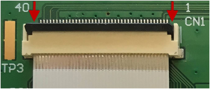
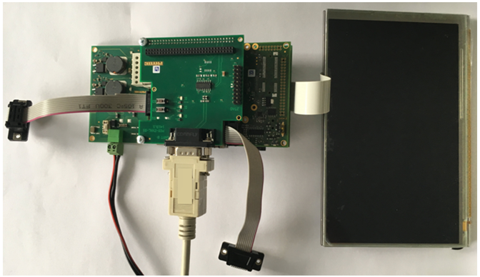
Connect one end of the FFC flex flat cable to the underside of the 7'' EDT display (AC158). There is a delicate clamp you need to pull up slightly before sliding the cable in.
Warning
Be very careful when inserting the cable into the display connector and the PEB-AV-07 adapter. This kind of display connector is easy to break if you use force!
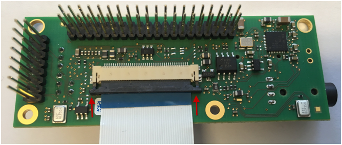
The clamp on the PEB-AV-07 voice recognition adapter pulls straight out to open the clamp. After inserting the cable, the clamp can then be pushed in to lock the cable in place.
PEB-AV-07 FFC cable clamp (open)Turn the display over. Connect the other end of the FFC flex flat cable to the PEB-AV-07 display adapter. The cable clamp needs to be pulled up at a 90°angle to open. After inserting the cable, push down the clamp to lock it.
EDT Display cable clamp (open)Turn the display so it is face-down. Plug the PEB-AV-07 display adapter into the phyBOARD-Mira i.MX 6.
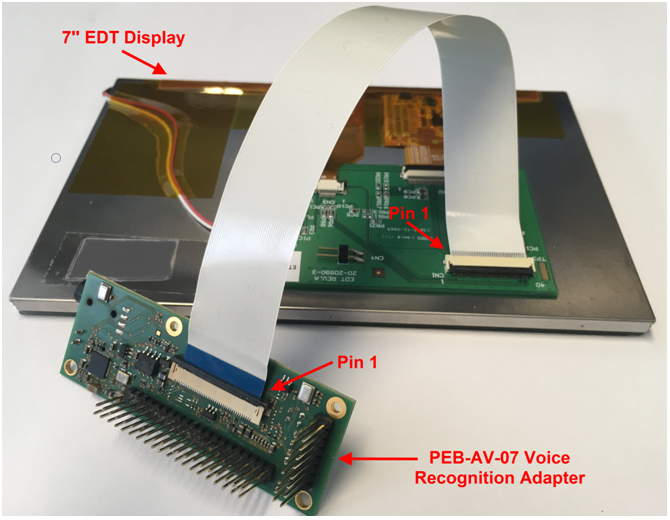
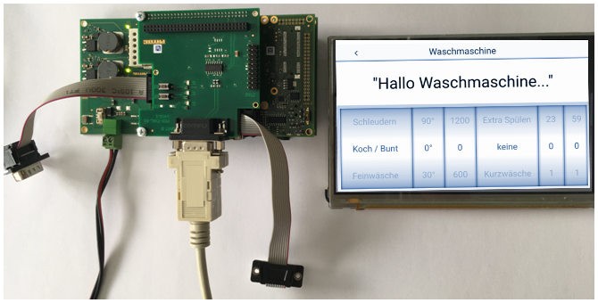
PEB-AV-07 Adapter and EDT Display Assembly (complete)Turn the display so it is face up. Plug the PEB-AV-07 display adapter into the phyBOARD-Mira i.MX 6.
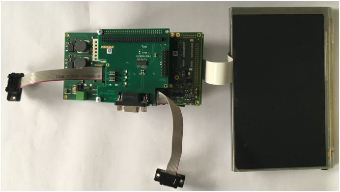
EDT Display Connected to phyBOARD-MiraIf you are using a phyBOARD-Mira i.MX 6 (PB-01501-xxxx), the display adapter needs to be plugged into the carrier board from the opposite side (from the bottom)!
Connect the RS-232 cable between your host PC and the phyBOARD-Mira debug adapter.
phyBOARD-Mira with Attached RS-232 Cable- Start your favorite terminal software (e.g. Minicom, or Tera Term) on your host PC and configure it for 115200 baud, 8 data bits, no parity, 1 stop bit (8n1), and no handshake.
- Connect the power supply to the power connector.
BSP Setup
The BSP has already been configured to support the display but it must be enabled as an expansion by editing the file config-expansions in the barebox environment. Please refer to the Yocto phyBOARD-Mira BSP Manual (L-814e.A4) for more information.
Open file config-expansions with:
bootloader$ edit /env/config-expansions
Change the comments of the following 2 lines from:
#. /env/expansions/im6-phytec-mira-peb-av-07
/env/expansions/mira.hdmi
to:
/env/expansions/mira-peb-av-07
#. /env/expansions/mira-hdmi
Save and exit the configuration file using CTRL+D and save the environment:
bootloader$ saveenv
Restart the board, and watch the boot. The login prompt will be shown at the end of the booting process:
Yogurt Vendor (Phytec Vendor Distribution) BSP-Yocto-Vendor-phyBOARD-Mira-PD18.1.0 phyboard-mira-imx6-2 ttymxc0
phyboard-mira-imx6-2 login:
phyBOARD-Mira Washing Machine Demo Start- The default login account is root with an empty password.
Revision History
Version | Changes | Date | Author |
|---|---|---|---|
LAN-078e_1 | First edition | 23.04.2018 | J. Tian |
LAN-078e.A2 | New pictures added | 13.02.2019 | J. Edmisten |
LAN-078e.A3 | PDF Version | 19.02.2019 | J. Edmisten |


