Gesamtbetrag:
zzgl. Mwst.
BSP Reference Manual - phyGATE-Sirius i.MX 6UL Alpha Kit (L-859e.A3)
Table of Contents
| Compatible BSP | BSP Release Type | BSP Release Date | BSP Status |
|---|---|---|---|
| BSP-Yocto-phyGate-Sirius-PD19.1.0 | Final Release (stable final Release) | 31 April 2020 | Released |
Compatible BSPs
Introduction to Yocto
Please read the Yocto Reference Manual for a better understanding of Yocto and this BSP.
Introduction to the BSP
Supported Hardware
For information on which boards and modules are supported by the release of PHYTEC’s i.MX 6UL / i.MX 6ULL BSP described herein, visit our web page at http://www.phytec.de/produkte/software/yocto/phytec-unified-yocto-bsp-releases/#unified-yocto-i-mx-6ul-bsp. Click the corresponding BSP release and look for the ordering number of your module in the column "Hardware Article Number". You can find the correct machine name in the corresponding cell under "Machine Name".
Supported Linux Kernel
The PHYTEC i.MX 6UL / i.MX 6ULL is supported by mainline-kernel 4.14.
Building the BSP
This section will guide you through the process of building the phyBOARD-Sirius BSP using the phyLinux script. For more details, see the section phyLinux Documentation in the Yocto Reference Manual. If you want to use our software without phyLinux and the Repo tool managed environment, you can find all Git repositories at:
git://git.phytec.de
Used barebox repository:
git://git.phytec.de/barebox
Our barebox version is based on the barebox mainline and adds only a few patches which will be sent upstream in the future.
Used Linux vendor kernel repository:
git://git.phytec.de/linux-imx
Used Linux mainline kernel repository:
git://git.phytec.de/linux-mainline
Our i.MX 6UL Linux kernel is based on the Linux stable kernel. The stable kernel repository can be found at:
git://git.kernel.org/pub/scm/linux/kernel/git/stable/linux-stable.git
You can find the adaption for the phyGATE-Sirius in a special repository:
git://git.phytec.de/meta-pbacd14
Get the BSP
- Create a fresh project directory:
host$ mkdir ~/yocto
- Download and run the phyLinux script:
host$ cd ~/yocto
host$ wget https://download.phytec.de/Software/Linux/Yocto/Tools/phyLinux
host$ wget https://download.phytec.de/Software/Linux/BSP-Yocto-phyGATE-Sirius-imx6ul/BSP-Yocto-phyGATE-Sirius-imx6ul-ALPHA2/BSP-Yocto-i.MX6UL-PD19.1.0-PBA-CD-14-2020-04-01.xml
host$ chmod +x phyLinux
host$ ./phyLinux init -x BSP-Yocto-i.MX6UL-PD19.1.0-PBA-CD-14-2020-04-01.xml
Basic Set-Up
There are a few important steps that have to be done before the main build process can start. These can be found in the Yocto Reference Manual.
- To set up the host, see Setting up the Host
- To set the Git configuration, see Git Configuration
Starting the Build Process
Refer to the section Start the Build.
BSP Images
All images generated by Bitbake are deployed to yocto/build/deploy/images/<machine>.
As an example, the following list shows all files generated for the i.MX 6 SOC, phygate-sirius-2-emmc machine:
- Barebox: barebox.bin
- Barebox configuration: barebox-defconfig
- Kernel: zImage
- Kernel device tree file: zImage-imx6ul-phytec-phygate-sirius-2-emmc.dtb
- Kernel configuration: zImage.config
- Root filesystem: phytec-headless-image-phygate-sirius-2-emmc.tar.gz, phytec-headless-image-phygate-sirius-2-emmc.ubifs, phytec-headless-image-phygate-sirius-2-emmc.ext4
- SD_CARD-Image: phytec-headless-image-phygate-sirius-2-emmc.sdcard
Booting the System
Booting from NAND Flash
NAND is the default boot source. To update the NAND Flash software, see Updating the Software.
Booting from eMMC
On phyGATE-Sirius, eMMC can be equipped instead of NAND flash. To update the software of the eMMC, see Updating the Software.
Booting from SD Card
Booting from an SD card is useful in several situations. For example, if the board does not start anymore due to a damaged bootloader. To boot from an SD card, the SD card must be formatted in a special way, as the i.MX 6UL ROM code does not use file systems. Instead, it expects the bootloader at a fixed location on the SD card.
There are two ways to create a bootable SD card. You can either use:
- a single prebuild SD card image, or
- four individual images (barebox-, kernel- and device tree image, and root filesystem)
Using a Single, Prebuild SD Card Image
The first option is to use the SD card image built by Yocto. This image has the ending *.sdcard and can be found under build/deploy/images/<MACHINE>/<IMAGENAME>-<MACHINE>.sdcard. It contains all BSP files in an already correctly formatted image and can be easily copied to the SD card by using the single Linux command dd.
You can also find ready-to-use *.sdcard images on our FTP server.
Warning
To create your bootable SD card with the dd command you must have root privileges. Because of that, you must be very careful when selecting the destination device for the dd command! All files on the selected destination device will be erased immediately without any further query! Consequently, having selected the wrong device can also erase your hard drive!
To create your bootable SD card, you must first find the correct device name and possible partitions of your SD card. Then unmount the partitions before you start copying the image to the SD card.
- In order to get the correct device name, first, remove your SD card and execute ls /dev.
- Next, insert your SD card and execute ls /dev again.
- Compare the two outputs to find the new device name(s) listed in the second output. These are the device names of the SD card (device and partitions if the SD card is formatted).
- In order to verify the device names found, execute the command dmesg. Within the last lines of its output, you should also find the device names, for example, sde (depending on your system).
Now that you have the device name /dev/<your_device> (e.g. /dev/sde), you can also recognize the partitions which must be unmounted if the SD card is formatted. In this case, you will also find /dev/<your_device> with an appended number (e.g. /dev/sde1) in the output. These represent the partition(s) to be unmounted.
- Unmount all partitions:
host$ umount /dev/<your_device><number>
- After having unmounted all devices with an appended number (<your_device><number>), you can create your bootable SD card:
host$ sudo dd if=<IMAGENAME>-<MACHINE>.sdcard of=/dev/<your_device> bs=1MB conv=fsync
using the device name (<your_device>) without appended number (e.g. sde) which stands for the whole device.
The parameter conv=fsync forces a sync operation on the device before dd returns. This ensures that all blocks are actually written to the SD card and do not remain in the memory.
Using Four Individual Images (barebox-, kernel- and device tree image, and root filesystem)
Instead of using the single prebuild SD card image, you can use the barebox, kernel, and device tree image together with the root filesystem to manually create a bootable SD card.
For this method, a new card must be set up with 2 partitions and 8 MB of free space at the beginning of the card. Use the following procedure with fdisk under Linux:
- Create a new FAT partition with partition id C. When creating the new partition, you must leave 8 MB of free space at the beginning of the card. When you go through the process of creating a new partition, fdisk lets you specify where the first sector starts. During this process, fdisk will tell you where the first sector on the disk begins. If, for example, the first sector begins at 2048, and each sector is 512 bytes. 8 MB / 512 bytes = 16384 sectors, which means your first sector should begin at 18432 to leave 8 MB of free space. The size of the FAT partition only needs to be big enough to hold the zImage which is only a few megabytes. To be safe we, recommend a size of 64 MB.
- Create a new Linux partition with partition id 83. Make sure you start this partition after the last sector of partition 1! By default, fdisk will try to use the first partition available on the disk, which in this example is 1000. However, this is our reserved space! You must use the remaining portion of the card for this partition.
- Write the new partition to the SD card and exit fdisk.
Example:
- Type:
host$ sudo fdisk -l /dev/sde
You will receive:
Disk /dev/sde: 3,8 GiB, 4025483264 bytes, 7862272 sectors
Units: sectors of 1 * 512 = 512 bytes
Sector size (logical/physical): 512 bytes / 512 bytes
I/O size (minimum/optimal): 512 bytes / 512 bytes
Disklabel type: dos
Disk identifier: 0xef6c9559

Device     Boot  Start     End Sectors  Size Id Type
/dev/sde1        18432  149503  131072   64M  c W95 FAT32 (LBA)
/dev/sde2       149504 7862271 7712768  3,7G 83 Linux
- Remove and reinsert the card. Otherwise, Linux will not recognize the new partitions created in the previous step.
- Create a file system on the partitions with (replace 'sde' with your device):
host$ sudo mkfs.vfat /dev/sde1
host$ sudo mkfs.ext4 -L "rootfs" /dev/sde2
Now, the images need to be copied to the SD card.
- Write the bootloader in front of the first partition (replace 'sde' with your device):
host$ sudo dd if=barebox.bin of=/dev/sde bs=512 skip=2 seek=2 conv=fsync
Mount the first partition (vfat) and copy the zImage and oftree file to it:
host$ sudo mount /dev/sd<X>1 /mnt
Warning
Make sure that the images are named as mentioned before, as the bootloader expects them exactly like that.
- If you want to boot the whole Linux from the SD card, mount the ext4 partition.
- Then, untar <IMAGENAME>-<MACHINE>.tar.gz rootfs image to it:
host$ sudo mount /dev/sd<X>2 /media
host$ sudo tar zxf <IMAGENAME>-<MACHINE>.tar.gz -C /media/
- Do not forget to properly unmount the SD card:
host$ sudo umount /media
Userspace Access via SSH-Login
To be able to access the userspace, you need to connect via SSH. Normally, access is possible by using the USB/UART interface via cable. However, due to design limitations, the cable cannot be plugged into this kit. The following section describes how to set up SSH-Login.
Tip
The default IP-Address of the target is: 192.168.3.11
First, connect the target via ethernet cable, open a command line, and type:
target$ ssh root@192.168.3.11
Type "yes" to accept. You can now access the target userspace.
target$ The authenticity of host '192.168.3.11 (192.168.3.11)' can't be established.
	    ECDSA key fingerprint is SHA256:haU+XXXXXXXXX/CTXXXXXXX.
        Are you sure you want to continue connecting (yes/no)?
Updating the Software
In this section, we explain how to use the barebox bootloader to update the barebox in both NAND and eMMC. The RAUC update mechanism is also introduced.
Warning
Flashing barebox can be dangerous. Before you start, please check to make sure you are using the correct bootloader version. NAND or eMMC for RAUC needs barebox access! More information can be found in Update NAND Flash and eMMC with RAUC
Updating the bootloader from Linux Userspace
It is possible to update the barebox bootloader from within the booted Linux userspace. This can only be done if certain specifications have been met.
Updating NAND Flash bootloader from Linux Userspace
To update the barebox on the NAND Flash from within Linux Userspace, the kobs-ng tool is used. It implements the same fail-safe update mechanism that is used with the barebox-update tool in the barebox. The following command requires the new barebox image to be copied to the target.
To update the barebox on the target type:
target$ kobs-ng init --search_exponent=1 barebox.bin
We also recommend erasing the environment of the old barebox. Otherwise, the new barebox will still use the old environment.
target$ flash_erase /dev/mtd1 0 0
After a reboot or power cycle, the new barebox will be used.
Updating eMMC bootloader from Linux Userspace
To update the bootloader on the eMMC from within Linux userspace, the dd command is used. This is similar to programming the bootloader to an SD card (see Booting from SD Card).
Some precautions need to be taken when updating the bootloader on the eMMC. The i.MX 6UL/6ULL ROM code expects the bootloader at a specific offset from the beginning of the eMMC. In front of that lies the partitioning table of the filesystem which follows the bootloader. So we have to make sure not to overwrite the partitioning table. Copying the bootloader to the eMMC can be achieved with:
target$ dd if=barebox.bin of=/dev/mmcblk1 bs=512 skip=2 seek=2 conv=fsync
We also recommend erasing the environment of the old barebox. Otherwise, the new barebox will still use the old environment:
target$ dd if=/dev/zero of=/dev/mmcblk0 bs=128k count=1 seek=7
After a reboot or power cycle, the new barebox will be used.
RAUC
Since the rocko release, the RAUC (Robust Auto-Update Controller) mechanism support has been added to yogurt. It controls the procedure of updating a device with new firmware. This includes updating the Linux kernel, Device Tree, and rootfs. It does not update the bootloader. For more information about RAUC, see https://rauc.readthedocs.io/en/latest/.
RAUC uses the barebox bootchooser and state framework (see Barebox Bootchooser and Barebox State-Framework for more information). It can be used in different update scenarios. Have a look at the use cases below and the example setup used in the BSP.
RAUC on i.MX 6UL/6ULL
With the BSP-Yocto-i.MX6UL-PD19.10 BSP release, RAUC (Robust Auto-Update Controller) can be used with NAND flash and eMMC flash. It is not enabled by default, but our example can be configured and activated with the instructions shown below. RAUC can be used in different update scenarios. As an example, we configured the BSP to use an A-B setup with two redundant systems.
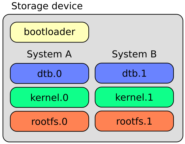
Storage Device Instructions
Creating RAUC Bundles
To update your system with RAUC, a RAUC bundle (.raucb) needs to be created. It contains all required images and scripts for the update and a RAUC manifest.raucm that describes the content of the bundle for the RAUC update on the target. The BSP includes a Yocto target that lets you build a RAUC bundle from your Yocto build.
To create the bundle with Yocto, run:
host$ bitbake phytec-qt5demo-bundle
in your Yocto build.
This results in the creation of a .raucb bundle file in the deploy/images/<machine-name>/phytec-qt5demo-bundle-<machine-name>.raucb file which can be used for an update described in the next chapter. There is no need to create a manifest.raucm manually as it is created automatically during the build of the bundle. But as a reference, the created manifest would look something like:
[update]
compatible=phyboard-segin-imx6ul-6
version=r1
description=PHYTEC rauc bundle based on BSP-Yocto-i.MX6UL-PD19.1.0
build=20190521073744

[image.rootfs]
sha256=586fe06c3d61ff04023a8cb3ddd6d246f8031ef0a05b1ed25213f7db8897ff2b
size=130023424
filename=phytec-qt5demo-image-phyboard-segin-imx6ul-6.ubifs

[image.kernel]
sha256=1a184e5356267277211eb690a151977d5f872b4ae8f0661ac5d963b4e83efdfa
size=6725712
filename=zImage-phyboard-segin-imx6ul-6.bin.img

[image.dtb]
sha256=2102512a05e37ba78e8dba06553be2f1c686e85acafbe5efd44e48c554b3f6db
size=34242
filename=imx6ull-phytec-segin-ff-rdk-nand.dtb.img
For more information about the manifest format, see https://rauc.readthedocs.io/en/latest/reference.html#manifest.
Tip
Currently, there is a bundle target for the phytec-qt5demo-image (phytec-qt5demo-bundle) and the phytec-headless-image (phytec-headless-bundle).
Update NAND Flash and eMMC with RAUC
To update the NAND flash and eMMC with RAUC, the RAUC bundle file previously created first needs to be copied to the board or to a memory device that can be mounted in Linux. One way is to copy the bundle file with scp, but make sure that there is enough space left on the board's filesystem. To do this, boot the target board to Linux and connect it via Ethernet to your host PC.
Run on the host:
host$ scp phytec-qt5demo-bundle-phyboard-segin-imx6ul-6.raucb root@192.168.3.11:/home/root/
On the target, you can verify the bundle:
target$ rauc info phytec-qt5demo-bundle-phyboard-segin-imx6ul-6.raucb
and get output similar to this:
rauc-Message: Reading bundle: /home/root/phytec-qt5demo-bundle-phyboard-segin-imx6ul-6.r
aucb
rauc-Message: Verifying bundle...
Compatible:     'phyboard-segin-imx6ul-6'
Version:        'r0'
Description:    'PHYTEC rauc bundle based on BSP-Yocto-i.MX6UL-PD19.1.0'
Build:          '20190521073744'
Hooks:          ''
3 Images:
(1)     phytec-qt5demo-image-phyboard-segin-imx6ul-6.ubifs
        Slotclass: rootfs
        Checksum:  586fe06c3d61ff04023a8cb3ddd6d246f8031ef0a05b1ed25213f7db8897ff2b
        Size:      130023424
        Hooks:
(2)     zImage-phyboard-segin-imx6ul-6.bin.img
        Slotclass: kernel
        Checksum:  1a184e5356267277211eb690a151977d5f872b4ae8f0661ac5d963b4e83efdfa
        Size:      6725712
        Hooks:
(3)     imx6ull-phytec-segin-ff-rdk-nand.dtb.img
        Slotclass: dtb
        Checksum:  2102512a05e37ba78e8dba06553be2f1c686e85acafbe5efd44e48c554b3f6db
        Size:      34242
        Hooks:
0 Files

Certificate Chain:
 0 Subject: /O=PHYTEC Messtechnik GmbH/CN=PHYTEC Messtechnik GmbH Development-1
   Issuer: /O=PHYTEC Messtechnik GmbH/CN=PHYTEC Messtechnik GmbH PHYTEC BSP CA Development
   SPKI sha256: E2:47:5F:32:05:37:04:D4:8C:48:8D:A6:74:A8:21:2E:97:41:EE:88:74:B5:F4:65:75:97:76:1D:FF:1D:7B:EE
   Not Before: Jan  1 00:00:00 1970 GMT
   Not After:  Dec 31 23:59:59 9999 GMT
 1 Subject: /O=PHYTEC Messtechnik GmbH/CN=PHYTEC Messtechnik GmbH PHYTEC BSP CA Development
   Issuer: /O=PHYTEC Messtechnik GmbH/CN=PHYTEC Messtechnik GmbH PHYTEC BSP CA Development
   SPKI sha256: AB:5C:DB:C6:0A:ED:A4:48:B9:40:AC:B1:48:06:AA:BA:92:09:83:8C:DC:6F:E1:5F:B6:FB:0C:39:3C:3B:E6:A2
   Not Before: Jan  1 00:00:00 1970 GMT
   Not After:  Dec 31 23:59:59 9999 GMT
To check the current state of the system, run:
target$ rauc status
and get output similar to:
Compatible:  phyboard-segin-imx6ul-6
Variant:
Booted from: system0
Activated:   rootfs.0 (system0)
slot states:
  dtb.1: class=dtb, device=/dev/ubi0_4, type=ubivol, bootname=(null)
      state=inactive, description=, parent=rootfs.1, mountpoint=(none)
  rootfs.0: class=rootfs, device=/dev/ubi0_2, type=ubifs, bootname=system0
      state=booted, description=, parent=(none), mountpoint=(none)
      boot status=good
  kernel.1: class=kernel, device=/dev/ubi0_3, type=ubivol, bootname=(null)
      state=inactive, description=, parent=rootfs.1, mountpoint=(none)
  rootfs.1: class=rootfs, device=/dev/ubi0_5, type=ubifs, bootname=system1
      state=inactive, description=, parent=(none), mountpoint=(none)
      boot status=good
  kernel.0: class=kernel, device=/dev/ubi0_0, type=ubivol, bootname=(null)
      state=active, description=, parent=rootfs.0, mountpoint=(none)
  dtb.0: class=dtb, device=/dev/ubi0_1, type=ubivol, bootname=(null)
      state=active, description=, parent=rootfs.0, mountpoint=(none)
To update the currently inactive system with the downloaded bundle, run:
target$ rauc install phytec-qt5demo-bundle-phyboard-segin-imx6ul-6.raucb
and reboot afterwards:
target$ reboot
Tip
When you update from a USB stick, make sure to remove the stick after a successful update before rebooting. If not, an automatic update will be started after each boot. This is due to the "Automatic Update from USB Flash Drive example" you can find below.
With the success of the update, RAUC automatically switches the active system to the newly updated system. Now during reboot, RAUC counts the boot attempts of the kernel and if it fails more often than specified in the state framework of the system, RAUC switches back to the old system and marks the new system as bad. If the boot attempt to the kernel is successful, the new system is marked as good and now the old system can be updated with the same instructions. After two successful rauc install and reboot, both systems are updated.
Change the active Boot Slot
It is possible to switch the active system manually:
target$ rauc status mark-active other
Now after a reboot or power cycle, the kernel starts from the alternate system.
Device Tree (DT)
Introduction
The following text briefly describes the Device Tree and can be found in the Linux kernel (linux/Documentation/devicetree/usage-model.txt).
"The "Open Firmware Device Tree", or simply Device Tree (DT), is a data structure and language for describing hardware. More specifically, it is a description of hardware that is readable by an operating system so that the operating system doesn't need to hard code details of the machine.

Structurally, the DT is a tree, or acyclic graph with named nodes, and nodes may have an arbitrary number of named properties encapsulating arbitrary data. A mechanism also exists to create arbitrary links from one node to another outside of the natural tree structure.

Conceptually, a common set of usage conventions, called 'bindings', is defined for how data should appear in the tree to describe typical hardware characteristics including data busses, interrupt lines, GPIO connections, and peripheral devices."
The kernel is a really good source for a DT introduction. An overview of the device tree data format can be found on the device tree usage page at devicetree.org:
http://devicetree.org/Device_Tree_Usage
PHYTEC phyGATE-Sirius i.MX 6UL BSP Device Tree Concept
The following section explains some rules we have defined on how to set up device trees for our i.MX 6 and i.MX 6UL SOC-based boards.
The device tree files are roughly divided into three layers:
- the SoC layer
- the module layer
- the baseboard layer
This resembles the physical properties of the hardware. For example, the same phyCORE-i.MX 6UL/ULLUL module can be used on the phyGATE-Sirius and the phyBOARD-Segin variants.
In each layer, multiple device trees include files.
An overview of the device tree hierarchy for the PHYTEC i.MX 6UL platforms is shown below.
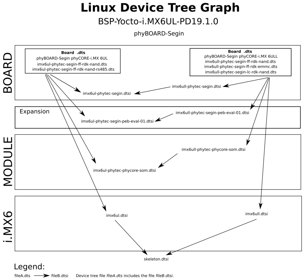
PHYTEC i.MX 6UL Device Tree Hierarchy
Note
To use the DT-Mods, barebox access is necessary! Description found here:Bootloader's DT Modifications
Accessing Peripherals
The following sections provide an overview of the supported hardware components and their corresponding operating system drivers. Further changes can be ported upon customer request.
To achieve maximum software re-use, the Linux kernel offers a sophisticated infrastructure, layering software components into board-specific parts. The BSP tries to modularize the kit features as far as possible, which means that when a customized baseboard or a customer-specific module is developed, most of the software support can be re-used without error-prone copy-and-paste. The kernel code corresponding to the boards can be found in device trees (DT) under:linux/arch/arm/boot/dts/*.dts*
In fact, software re-use is one of the most important features of the Linux kernel (especially the ARM implementation), which always had to fight with an insane number of possibilities of the System-on-Chip CPUs. The whole board-specific hardware is described in DTs and is not part of the kernel image itself. The hardware description is in its own separate binary, called device tree blob (DTB) (section Bootloader's DT Modifications).
Please read section PHYTEC phyGATE-Sirius i.MX 6UL BSP Device Tree Concept to get an understanding of our i.MX 6UL BSP device tree model. The following sections provide an overview of the supported hardware components and their operating system drivers on the i.MX 6UL and i.MX 6ULL platform.
i.MX 6UL Pin Muxing
The i.MX 6UL SOC contains many peripheral interfaces. In order to reduce package size and lower overall system cost while maintaining maximum functionality, many of the i.MX 6UL terminals can multiplex up to eight signal functions. Although there are many combinations of pin multiplexing possible, only a certain number of sets (called IO sets) are valid due to timing limitations. These valid IO sets were carefully chosen to provide as many application scenarios as possible for the user.
Please refer to the NXP i.MX 6UL and i.MX 6ULL Reference Manuals for more information about the specific pins and the muxing capabilities:
- for the i.MX 6Ultra Lite
http://www.nxp.com/docs/en/reference-manual/IMX6ULRM.pdf
- for the i.MX 6ULL
http://www.nxp.com/docs/en/reference-manual/IMX6ULLRM.pdf
The IO set configuration, also called muxing, is done in the Device Tree. The driver pinctrl-imx reads the DT's node "fsl,pins" and does the appropriate pin muxing. The following is an example of the pin muxing of the UART1 device in imx6ul-phytec-phycore-som.dtsi:
       pinctrl_uart1: uart1grp {
               fsl,pins = <
                       MX6UL_PAD_UART1_TX_DATA__UART1_DCE_TX   0x1b0b1
                       MX6UL_PAD_UART1_RX_DATA__UART1_DCE_RX   0x1b0b1
               >;
       };
The first part of the string MX6UL_PAD_UART1_TX_DATA__UART1_DCE_TX names the pad (PAD_UART1_TX_DATA). The second part of the string (UART1_DCE_TX) is the desired muxing option for this pad. The pad setting value (hex value on the right) is explained in:
linux/Documentation/devicetree/bindings/pinctrl/fsl,imx6ul-pinctrl.txt
In this example, the pad setting value 0x1b0b1 means the pin is configured with: PAD_CTL_HYS, PAD_CTL_SRE_SLOW, PAD_CTL_DSE_40ohm, PAD_CTL_SPEED_MED, PAD_CTL_PUS_100K_UP, PAD_CTL_PUE and PAD_CTL_PKE. This example is defined in:
linux/arch/arm/boot/dts/imx6ul-pinfunc.h
for the i.MX6 6UL.
Serial TTYs
The i.MX 6UL SOC provides up to 8 UART units. PHYTEC boards support different numbers of these UART units. The debug UART is configured as 115200 8N1 (115200 baud, 8 data bits, no parity bit, 1 stop bit). The other UARTs will have default settings, which normally will be 9600 baud. The phyGATE-Sirius use the UART1 (ttymxc0) as standard console output.
- From the command line prompt of Linux user space, you can easily check the availability of other UART interfaces with:
target$ echo "test" > /dev/ttymxc4
Be sure that the baud rate is set correctly on both the host and target. In order to get the currently configured baud rate, you can use the command stty on the target. The following example shows how to copy all serial settings from ttymxc0 to ttymxc4.
- First, get the current parameters with:
target$ stty -F /dev/ttymxc0 -g
5500:5:1cb2:a3b:3:1c:7f:15:4:0:1:0:11:13:1a:0:12:f:17:16:0:0:0:0:0:0:0:0:0:0:0:0:0:0:0:0
- Now use the output from the stty command above as the argument for the next command:
target$ stty -F /dev/ttymxc4 5500:5:1cb2:a3b:3:1c:7f:15:4:0:1:0:11:13:1a:0:12:f:17:16:0:0:0:0:0:0:0:0:0:0:0:0:0:0:0:0
- You can also write both in just one command in order to make it more simple:
target$ stty -F /dev/ttymxc4 $(stty -g < /dev/ttymxc0)
Network
The phyGATE-Sirius has 2 x 10/100 Mbit ethernet ports. However, all interfaces offer a standard Linux network port which can be programmed using the BSD socket interface.
The whole network configuration is handled by the systemd-networkd daemon. The relevant configuration files can be found on the target in /lib/systemd/network/ and also in the BSP in meta-yogurt/recipes-core/systemd/systemd/. IP addresses can be configured within *.network files. The default IP addresses and netmasks for eth0 and eth1 are:
eth0: 192.168.3.11/24
eth1: 192.168.4.11/24
CAN Bus
The phyGATE-Sirius-i.MX 6UL provides a CAN interface, which is supported by drivers using the Linux standard CAN framework SocketCAN. Using this framework, CAN interfaces can be programmed with the BSD socket API.
The CAN (Controller Area Network) bus offers a low-bandwidth, prioritized message Fieldbus for serial communication between microcontrollers. Unfortunately, CAN was not designed with the ISO/OSI layer model in mind, so most CAN APIs available throughout the industry do not support a clean separation between the different logical protocol layers (as, for example, known from Ethernet).
The SocketCAN framework for Linux extends the BSD socket API concept toward the CAN bus. Using this framework, the CAN interfaces can be programmed with the BSD socket API and behaves like an ordinary Linux network device, with some additional features special to CAN.
- For example, use:
target$ ip link
to see if the interface is up or down. The given MAC and IP addresses are arbitrary and obsolete.
- To get the information on can0 (which represents i.MX 6UL’s CAN module FLEXCAN1) (such as bit rate and error counters), type:
target$ ip -d -s link show can0
The information for can0 will look like the following:
2: can0: <NOARP,ECHO> mtu 16 qdisc pfifo_fast state DOWN mode DEFAULT group default qlen 10
    link/can  promiscuity 0
    can state STOPPED (berr-counter tx 0 rx 0) restart-ms 0
          bitrate 10000 sample-point 0.866
          tq 6666 prop-seg 6 phase-seg1 6 phase-seg2 2 sjw 1
          flexcan: tseg1 4..16 tseg2 2..8 sjw 1..4 brp 1..256 brp-inc 1
          clock 30000000
          re-started bus-errors arbit-lost error-warn error-pass bus-off
          0          0          0          0          0          0
    RX: bytes  packets  errors  dropped overrun mcast
    0          0        0       0       0       0
    TX: bytes  packets  errors  dropped carrier collsns
    0          0        0       0       0       0
The output contains a standard set of parameters also shown for Ethernet interfaces, so not all of these are necessarily relevant for CAN (for example, the MAC address). The following output parameters contain useful information:
| Field | Description |
|---|---|
| can0 | Interface Name |
| NOARP | CAN cannot use ARP protocol |
| MTU | Maximum Transfer Unit |
| RX packets | Number of Received Packets |
| TX packets | Number of Transmitted Packets |
| RX bytes | Number of Received Bytes |
| TX bytes | Number of Transmitted Bytes |
| errors... | Bus Error Statistics |
Ethernet Interfaces Output Parameters
The CAN configuration is done in the systemd configuration file /lib/systemd/system/can0.service. For a persistent change of, as an example, the default bitrates change the configuration in the BSP under meta-yogurt/recipes-core/systemd/systemd/can0.service in the root filesystem instead and rebuild the root filesystem.
[Unit]
Description=can0 interface setup

[Service]
Type=simple
RemainAfterExit=yes
ExecStart=/sbin/ip link set can0 up type can bitrate 500000
ExecStop=/sbin/ip link set can0 down

[Install]
WantedBy=basic.target
The can0.service is started by default after boot. You can start and stop it with:
target$ systemctl stop can0.service
target$ systemctl start can0.service
You can send messages with cansend or receive messages with candump:
target$ cansend can0 123#45.67
target$ candump can0
To generate random CAN traffic for testing purposes, use cangen.
target$ cangen
See cansend --help and candump --helpmessages for further information on options and usage.
MMC/SD Card
All i.MX 6 kits support a slot for Secure Digital and MultiMedia Cards to be used as general-purpose block devices. These devices can be used in the same way as any other block device.
Warning
These kinds of devices are hot-pluggable. Nevertheless, you must make sure not to unplug the device while it is still mounted. This may result in data loss.
After inserting an MMC/SD card, the kernel will generate new device nodes in /dev. The full device can be reached via its /dev/mmcblk0 device node and MMC/SD card partitions will show up:
/dev/mmcblk0p<Y>
<Y> counts as the partition number starting from 1 to the max. count of partitions on this device. The partitions can be formatted with any kind of file system and also handled in a standard manner, e.g. the mount and umount command work as expected.
Tip
These partition device nodes will only be available if the card contains a valid partition table (”hard disk” like handling). If it does not contain one, the whole device can be used as a file system (”floppy” like handling). In this case /dev/mmcblk0 must be used for formatting and mounting.
------------------
The cards are always mounted as being writable. Write-protection of MMC/SD cards is only recognized on the phyFLEX Carrier Board.
DT configuration for the MMC interface in arch/arm/boot/dts/imx6qdl-phytec-mira.dtsi:
&iomuxc {
	pinctrl_usdhc1: usdhc1grp {
		fsl,pins = <
			MX6QDL_PAD_SD1_CMD__SD1_CMD		0x170f9
			MX6QDL_PAD_SD1_CLK__SD1_CLK		0x100f9
			MX6QDL_PAD_SD1_DAT0__SD1_DATA0		0x170f9
			MX6QDL_PAD_SD1_DAT1__SD1_DATA1		0x170f9
			MX6QDL_PAD_SD1_DAT2__SD1_DATA2		0x170f9
			MX6QDL_PAD_SD1_DAT3__SD1_DATA3		0x170f9
			MX6QDL_PAD_EIM_BCLK__GPIO6_IO31		0xb0b1  /* CD */
		>;
	};
};

&usdhc1 {
	pinctrl-names = "default";
	pinctrl-0 = <&pinctrl_usdhc1>;
	cd-gpios = <&gpio6 31 GPIO_ACTIVE_LOW>;
	no-1-8-v;
	status = "disabled";
};
Resize the ext4 Root Filesystem
Warning
Pay attention to the RAUC-Partitions. They can be destroyed.
parted and resize2fs can be used to expand the root filesystem. The example works for any block device such as eMMC, SD card, or hard disk.
- Get the current device size (from SD card in this case):
target$ parted -m /dev/mmcblk0 unit B print
The output looks like this:
BYT;
/dev/mmcblk0:3991928832B:sd/mmc:512:512:msdos:SD USD:;
1:4194304B:12582911B:8388608B:::lba;
2:12582912B:138412031B:125829120B:ext4::;
- Now use the size of the device minus one as the new end of the second partition (e.g. 3991928832B):
target$ parted /dev/mmcblk0 resizepart 2 3991928831B
- After expanding the partition size, resize the ext4 file system in the partition:
target$ resize2fs /dev/mmcblk0p2
The command's output looks like this:
resize2fs 1.42.9 (28-Dec-2013)
Filesystem at /dev/mmcblk0p2 is mounted on /; on-line resizing required
old_desc_blocks = 1, new_desc_blocks = 15
The filesystem on /dev/mmcblk0p2 is now 3886080 blocks long.
Increasing the file system size can be done while it is mounted. An on-line resizing operation is performed. However, you can also boot the board from internal memory (NAND or eMMC) and then resize the file system on the SD card partition while it is not mounted.
eMMC Devices
The phyCORE-i.MX 6UL/ULL can be populated with an eMMC memory chip as the main storage instead of the NAND Flash. eMMC devices contain raw MLC memory cells (section Enable pseudo-SLC Mode) combined with a memory controller, that handles ECC and wear leveling. They are connected via an MMC/SD interface to the i.MX 6 and are represented as block devices in the Linux kernel like SD cards, flash drives, or hard disks.
The electric and protocol specification is provided by JEDEC (https://www.jedec.org/standards-documents/technology-focus-areas/flash-memory-ssds-ufs-emmc/e-mmc). The eMMC manufacturer's datasheet is mostly relatively short and meant to be read together with the supported version of the JEDEC eMMC standard.
eMMC Partitions
Note
In normal cases, the eMMC has two partitions, boot, and root. The boot includes both oftree and kernel. Root includes the rootfs only. If you want to use additional partitions for something else (for example data), you need barebox access to set it up. More information can be found in section eMMC (Boot-)Partitions.
Enable pseudo-SLC Mode
eMMC devices use MLC memory cells (https://en.wikipedia.org/wiki/Multi-level_cell) to store the data. Compared with SLC memory cells used in NAND Flashs, MLC memory cells have lower reliability and a higher error rate at lower costs.
If you prefer reliability over storage capacity, you can enable the pseudo-SLC mode or SLC mode. The method used here employs the enhanced attribute, described in the JEDEC standard, which can be set for continuous regions of the device. The JEDEC standard does not specify the implementation details and the guarantees of the enhanced attribute. This is left to the chipmaker. For the Micron chips, the enhanced attribute increases the reliability but also halves the capacity.
Warning
When enabling the enhanced attribute on the device, all data will be lost.
The following sequence shows how to enable the enhanced attribute.
- First obtain the current size of the eMMC device with:
target$ parted -m /dev/mmcblk3 unit B print
You will receive:
BYT;
/dev/mmcblk3:3783262208B:sd/mmc:512:512:unknown:MMC MMC04G:;
As you can see this device has 3783262208 Byte = 3608.0 MiB.
- To get the maximum size of the device after pseudo-SLC is enabled use:
target$ mmc extcsd read /dev/mmcblk3 | grep ENH_SIZE_MULT -A 1
which shows, for example:
Max Enhanced Area Size [MAX_ENH_SIZE_MULT]: 0x0001c3 i.e. 1847296 KiB
--
Enhanced User Data Area Size [ENH_SIZE_MULT]: 0x000000 i.e. 0 KiB
Here the maximum size is 1847296 KiB = 1804 MiB.
- Now, you can set enhanced attribute for the whole device, e.g. 1847296 KiB, by typing:
target$ mmc enh_area set -y 0 1847296 /dev/mmcblk3
You will get:
Done setting ENH_USR area on /dev/mmcblk3
setting OTP PARTITION_SETTING_COMPLETED!
Setting OTP PARTITION_SETTING_COMPLETED on /dev/mmcblk3 SUCCESS
Device power cycle needed for settings to take effect.
Confirm that PARTITION_SETTING_COMPLETED bit is set using 'extcsd read' after a power cycle
- To ensure that the new setting has taken over, shut down the system:
target$ poweroff
and perform a power cycle. It is recommended that you verify the settings now.
- First, check the value of ENH_SIZE_MULT which must be 1847296 KiB:
targe$ mmc extcsd read /dev/mmcblk3 | grep ENH_SIZE_MULT -A 1
You should receive:
Max Enhanced Area Size [MAX_ENH_SIZE_MULT]: 0x0001c3
 i.e. 1847296 KiB
--
Enhanced User Data Area Size [ENH_SIZE_MULT]: 0x0001c3
 i.e. 1847296 KiB
- Finally, check the size of the device, in this example it should be 1891631104 Byte = 1804.0 MiB, with:
target$ parted -m /dev/mmcblk3 unit B print
BYT;
/dev/mmcblk3:1891631104B:sd/mmc:512:512:unknown:MMC MMC04G:;
- Now you can flash your new image.
Further reference: https://www.micron.com/support/faqs → Products → NAND Flash → eMMC → question "What are the enhanced technology features mentioned in JEDEC specification, and what are the benefits?"
Warning
Disabling pseudo-SLC Mode is not possible
Extended CSD Register
eMMC devices have an extensive amount of extra information and settings that are available via the Extended CSD registers. For a detailed list of the registers, see the manufacturer datasheets and the JEDEC standard.
- In the Linux userspace, you can query the registers:
target$ mmc extcsd read /dev/mmcblk3
You will see:
=============================================
  Extended CSD rev 1.5 (MMC 4.41)
=============================================

Card Supported Command sets [S_CMD_SET: 0x01]
[...]
- In the bootloader you can use:
bootloader$ detect mmc3
if the device is not probed yet, then:
bootloader$ mmc_extcsd /dev/mmc3
Enable Background Operations (BKOPS)
In contrast to raw NAND Flash, an eMMC device contains a Flash Transfer Layer (FTL) that handles the wear leveling, block management, and ECC of the raw MLC cells. This requires some maintenance tasks, for example erasing non-used blocks, that are performed regularly. These tasks are called Background Operations (BKOPS).
In the default case (which depends on the chip) the background operations are not executed periodically, which impacts the worst-case read and write latency. Therefore, the JEDEC Standard version v4.41 specifies a method that the host can issue BKOPS manually. See the JEDEC Standard chapter Background Operations and the description of registers BKOPS_EN (Reg: 163) and BKOPS_START (Reg: 164) in the eMMC datasheet for more details.
Meaning of Register BKOPS_EN (Reg: 163) Bit MANUAL_EN (Bit 0):
- Value 0: The host does not support the manual trigger of BKOPS. Device write performance suffers.
- Value 1: The host does support the manual trigger of BKOPS. It will issue BKOPS from time to time when it does not need the device.
The mechanism to issue background operations has been implemented in the Linux kernel since v3.7. You only have to enable BKOPS_EN on the eMMC device (see below for details). The JEDEC standard v5.1 introduces a new automatic BKOPS feature. It frees the host to trigger the background operations regularly because the device starts BKOPS itself when it is idle (see the description of bit AUTO_EN in register BKOPS_EN (Reg: 163)).
eMMC chips deployed by PHYTEC currently do not support the new standard v5.1. The Linux kernel and userspace tool mmc do not support this feature.
- To check whether BKOPS_EN is set, execute:
target$ mmc extcsd read /dev/mmcblk3 | grep BKOPS_EN
The output will be, for example:
Enable background operations handshake [BKOPS_EN]: 0x01
Here BKOPS_EN is enabled. The host will issue background operations from time to time.
There is also a kernel boot message showing if BKOPS_EN is not set:
mmc1: MAN_BKOPS_EN bit is not set
- To set the BKOPS_EN bit, execute:
target$ mmc bkops enable /dev/mmcblk3
- To ensure that the new setting has taken over and the kernel triggers BKOPS by itself, shut down the system with:
target$ poweroff
and perform a power cycle.
Warning
The BKOPS_EN bit is one-time-programmable only. It cannot be reversed.
Reliable Write
There are two different Reliable Write options:
- Reliable Write option for a whole eMMC device/partition
- Reliable Write for single write transactions
Tip
Do not confuse eMMC partitions with partitions of a DOS MBR, or GPT partition table (see the previous section).
The first Reliable Write option can be enabled with the mmc tool:
target$ mmc --help
[...]
mmc write_reliability set <-y|-n> <partition> <device>
The second Reliable Write option is the configuration bit Reliable Write Request parameter (bit 31) in command CMD23. It has been used in the kernel since v3.0 by file systems, e.g. ext4 for the journal, and userspace applications such as fdisk for the partition table. In the Linux kernel source code, it is handled via flag REQ_META.
Conclusion: ext4 file system with mount option data=journal should be safe against power cuts. The file system check can recover the file system after a power failure, but data that was written just before the power cut may be lost. At a minimum, a consistent state of the file system can be recovered. To ensure data consistency for the files of an application, the system functions fdatasync, or fsync should be used in the application.
Resize the ext4 Root Filesystem
parted and resize2fs can be used to expand the root filesystem. The example works for any block device such as eMMC, SD card, or hard disk.
- Get the current device size (from eMMC in this case):
target$ parted -m /dev/mmcblk3 unit B print
The output looks like this:
BYT;
/dev/mmcblk3:3991928832B:sd/mmc:512:512:msdos:SD USD:;
1:4194304B:12582911B:8388608B:::lba;
2:12582912B:138412031B:125829120B:ext4::;
- Now use the size of the device minus one as the new end of the second partition (e.g. 3991928832B):
target$ parted /dev/mmcblk3 resizepart 2 3991928831B
- After expanding the partition size, resize the ext4 file system in the partition:
target$ resize2fs /dev/mmcblk3p2
The command's output looks like this:
resize2fs 1.42.9 (28-Dec-2013)
Filesystem at /dev/mmcblk3p2 is mounted on /; on-line resizing required
old_desc_blocks = 1, new_desc_blocks = 15
The filesystem on /dev/mmcblk3p2 is now 3886080 blocks long.
Increasing the file system size can be done while it is mounted. An on-line resizing operation is performed. But you can also boot the board from the SD card and then resize the file system on the eMMC partition while it is not mounted.
Erase the Device
It is possible to erase the eMMC device directly rather than overwriting it with zeros. The eMMC block management algorithm will erase the underlying MLC memory cells or mark these blocks as discard. The data on the device is lost and will be read back as zeros.
- After booting from the SD card execute:
target$ blkdiscard --secure /dev/mmcblk3
The option --secure ensures that the command waits until the eMMC device has erased all blocks.
Tip
dd if=/dev/zero of=/dev/mmcblk3 also destroys all information on the device, but is bad for wear leveling and takes much longer!
For raw NAND flashes, the same could be achieved with the command flash_erase.
Additional Software in the BSP
In the BSP, you will also find the tool flashbench which allows the user to get the page size and erase block size.
- E.g. type:
target$ flashbench -a /dev/mmcblk3 --blocksize=1024
This will, for example, result in:
align 1073741824	pre 779µs	on 1.21ms	post 768µs	diff 439µs
align 536870912	pre 855µs	on 1.29ms	post 858µs	diff 433µs
align 268435456	pre 846µs	on 1.29ms	post 821µs	diff 454µs
align 134217728	pre 812µs	on 1.25ms	post 822µs	diff 429µs
align 67108864	pre 846µs	on 1.29ms	post 832µs	diff 452µs
align 33554432	pre 830µs	on 1.24ms	post 807µs	diff 422µs
align 16777216	pre 841µs	on 1.26ms	post 842µs	diff 418µs
align 8388608	pre 842µs	on 1.27ms	post 814µs	diff 446µs
align 4194304	pre 838µs	on 1.28ms	post 842µs	diff 436µs
align 2097152	pre 827µs	on 928µs	post 834µs	diff 97.9µs
align 1048576	pre 826µs	on 921µs	post 827µs	diff 94.5µs
align 524288	pre 828µs	on 924µs	post 841µs	diff 89.6µs
align 262144	pre 835µs	on 903µs	post 841µs	diff 65.1µs
align 131072	pre 842µs	on 949µs	post 853µs	diff 101µs
align 65536	pre 854µs	on 959µs	post 858µs	diff 103µs
align 32768	pre 844µs	on 954µs	post 869µs	diff 97.2µs
align 16384	pre 862µs	on 962µs	post 847µs	diff 108µs
align 8192	pre 849µs	on 946µs	post 847µs	diff 98.5µs
align 4096	pre 858µs	on 953µs	post 855µs	diff 96.9µ2s
align 2048	pre 845µs	on 936µs	post 846µs	diff 90.8µs
For an explanation of how to interpret the output, see https://git.linaro.org/people/arnd.bergmann/flashbench.git/blob/HEAD:/README#l1
NAND Flash
PHYTEC i.MX 6UL modules are equipped with raw NAND memory, which is used as media for storing Linux, DTB, and root filesystem including applications and their data files. The NAND Flash is connected to the General Purpose Media Interface (GPMI) of the i.MX 6UL. The NAND Flash type and size is automatically detected via the Open NAND Flash Interface (ONFI) during boot.
This type of media is managed by the UBI file system. This file system uses compression and decompression on the fly to increase the quantity of data stored. In Linux user space, the NAND Flash partitions start with /dev/mtdblock0. Only the /dev/mtdblock2 on the PHYTEC modules has a file system, meaning that the other partitions cannot be mounted to the root filesystem. The only way to access them is by flashing a prepared flash image into the corresponding /dev/mtd device node.
The partitions of a NAND Flash are defined in all DTs, but the barebox bootloader overwrites only the partitions of the kernel device tree. Changing the partitions has to be done either in the barebox DT or the barebox environment. How to modify the partitions during runtime in the barebox environment is described in section Changing MTD Partitions. Adding new partitions can be done by creating a new partition node in the corresponding board device tree (PHYTEC phyGATE-Sirius i.MX 6UL BSP Device Tree Concept).
The property label defines the name of the partition. The reg value defines the offset and size of a partition. Do not forget to update all following partitions when adding a partition or changing a partition's size.
The partitions are defined in the DT. For example, imx6ull-phytec-phycore-som.dtsi in the barebox:
&gpmi {
        pinctrl-names = "default";
        pinctrl-0 = <&pinctrl_gpmi_nand>;
        nand-on-flash-bbt;
        fsl,no-blockmark-swap;
        status = "okay";

        #address-cells = <1>;
        #size-cells = <1>;

        partition@0 {
                label = "barebox";
                reg = <0x0 0x400000>;
        };

        partition@400000 {
                label = "barebox-environment";
                reg = <0x400000 0x100000>;
        };

        partition@500000 {
                label = "root";
                reg = <0x500000 0x0>;
        };
};
LEDs
I/O pins like LEDs can be accessed from userspace. In the Alpha version of this BSP, they are used as GPIOs. Please see section GPIOs on how to access the LEDs
GPIOs
PHYTEC boards often have a set of pins specially dedicated as a user I/Os. Those pins are connected directly to i.MX 6 UL pins and are muxed as GPIOs. They are directly usable in Linux user space. The processor has organized its GPIOs into six banks (GPIO1 – GPIO6) of 32 GPIOs each and one bank with 14 GPIOs. gpiochip0, gpiochip32, gpiochip64, gpiochip96, gpiochip128, gpiochip160, and gpiochip192 are the sysfs representation of these internal i.MX 6 GPIO banks GPIO1 – GPIO7.
The GPIOs are identified as GPIO<X>_<Y> (e.g. GPIO5_07). <X> identifies the GPIO bank and counts from 1 to 7, while <Y> stands for the GPIO within the bank. <Y> is being counted from 0 to 31 (32 GPIOs on each bank). By contrast, the Linux kernel uses a single integer to enumerate all available GPIOs in the system. The formula to calculate the right number is:
Linux GPIO number = (<X> - 1) * 32 + <Y>
accessing GPIOs from user space is done using the sysfs path /sys/class/gpio/. There, you need to register the GPIOs that you want to use by writing their numbers into the file export, e.g.:
- target$ echo 8 > /sys/class/gpio/export
This will create a new subdirectory gpio8. The two files direction and value in the new subdirectory enable control of the GPIO.
- For example, to use the newly created GPIO 8 as output and to toggle it, execute:
target$ echo out > /sys/class/gpio/gpio8/direction
target$ echo 1 > /sys/class/gpio/gpio8/value
target$ echo 0 > /sys/class/gpio/gpio8/value
On the phyBOARD-Sirius, this will toggle one of the status LEDs. The second LED is controlled by GPIO 9.
- To use, for example, GPIO 133 as input, execute the following commands:
target$ echo 133 > /sys/class/gpio/export
target$ echo in > /sys/class/gpio/gpio133/direction
target$ cat /sys/class/gpio/gpio133/value
This reads the status of DIN1 on connector X14. DIN2 can be read by accessing GPIO 1.
Warning
Some of the user IOs are used for special functions on the carrier boards (e.g. GPIO5_8, GPIO1_9, and GPIO7_12 on the PBA-B-01 CB). Before using a user IO, refer to the schematic or the hardware manual of your board to ensure that it is not already in use.
Pinmuxing of some GPIO pins in the device tree imx6qdl-phytec-pbab01.dtsi:
                pinctrl_hog: hoggrp {
                        fsl,pins = <
                                MX6QDL_PAD_EIM_D23__GPIO3_IO23    0x80000000
                                MX6QDL_PAD_DISP0_DAT3__GPIO4_IO24 0x80000000 /* SPI NOR chipselect */
                                MX6QDL_PAD_SD4_DAT1__GPIO2_IO09   0x80000000 /* PMIC interrupt */
                                MX6QDL_PAD_ENET_TXD0__GPIO1_IO30  0x80000000 /* Green LED */
                                MX6QDL_PAD_EIM_EB3__GPIO2_IO31    0x80000000 /* Red LED */
                                MX6QDL_PAD_GPIO_8__GPIO1_IO08     0x80000000
[...]
Relay Outputs
The phyGATE-Sirius has relays that are controlled by GPIOs. The relay for connector X6 is controlled by GPIO 112; the relay for connector X8 by GPIO 137. Please refer to section GPIOs for information on how to access GPIOs.
I²C Bus
The i.MX 6UL contains four Multimaster fast-mode I²C modules called I2C1. This chapter will describe the basic device usage of some of the I²C devices integrated on our phyGATE-Sirius.
EEPROM
It is possible to read and write directly to the device:
/sys/class/i2c-dev/i2c-0/device/0-0052/eeprom
- To read and print the first 1024 bytes of the EEPROM as a hex number, execute:
target$ dd if=/sys/class/i2c-dev/i2c-0/device/0-0052/eeprom bs=1 count=1024 | od -x
- To fill the whole EEPROM with zeros, use:
target$ dd if=/dev/zero of=/sys/class/i2c-dev/i2c-0/device/0-0052/eeprom bs=4096 count=1
This operation takes some time because the EEPROM is relatively slow.
RTC
RTCs can be accessed via /dev/rtc*. Because PHYTEC boards often have more than one RTC, there might be more than one RTC device file.
- To find out the name of the RTC device, you can read its sysfs entry with:
target$ cat /sys/class/rtc/rtc*/name
You will get, for example:
rv3028
20cc000.snvs:snvs-r
Tip
This will list all RTCs including the non-I²C RTCs. Linux assigns RTC device IDs based on the device tree /aliases entries if present.
As time is set according to the value of rtc0 during system boot, rtc0 should always be the RTC that is being backed up. Date and time can be manipulated with the hwclock tool, using the -w (systohc) and -s (hctosys) options. To set the date, first, use date and then run hwclock -w -u to store the new date into the RTC. For more information about this tool, refer to the manpage of hwclock.
USB Host Controller
The USB controller of the i.MX 6UL SOC provides a low-cost connectivity solution for numerous consumer portable devices by providing a mechanism for data transfer between USB devices with a line/bus speed up to 480 Mbps. The USB subsystem has two independent USB controller cores. The phyGATE-Sirius i.MX 6UL BSP includes support for mass storage devices, keyboards, and mice. Other USB-related device drivers must be enabled in the kernel configuration on demand.
Due to udev, all mass storage devices connected get unique IDs and can be found in /dev/disks/by-id. These IDs can be used in /etc/fstab to mount the different USB memory devices in different ways.
USB OTG
Most PHYTEC boards provide a USB OTG interface. USB OTG ports automatically act as a USB device or USB host. The mode depends on the USB hardware attached to the USB OTG port. If, for example, a USB mass storage device is attached to the USB OTG port, the device will show up as /dev/sda.
USB Device
In order to connect the board as a USB device to a USB host port (for example a PC), you need to configure the appropriate USB gadget. With USB configfs, you can define the parameters and functions of the USB gadget. The BSP includes USB configfs support as a kernel module.
target$ modprobe libcomposite
Example:
- Define the parameters like the USB vendor and product IDs. Set information strings for the English (0x409) language:
target$ cd /sys/kernel/config/usb_gadget/
target$ mkdir g1
target$ cd g1/
target$ echo "0x1d6b" > idVendor
target$ echo "0x0104" > idProduct
target$ mkdir strings/0x409
target$ echo "0123456789" > strings/0x409/serialnumber
target$ echo "Foo Inc." > strings/0x409/manufacturer
target$ echo "Bar Gadget" > strings/0x409/product
- Create a file for the mass storage gadget:
target$ dd if=/dev/zero of=/tmp/file.img bs=1M count=64
- Create the functions you want to use:
target$ cd /sys/kernel/config/usb_gadget/g1
target$ mkdir functions/acm.GS0
target$ mkdir functions/ecm.usb0
target$ mkdir functions/mass_storage.0
target$ echo /tmp/file.img > functions/mass_storage.0/lun.0/file
- ACM: Serial gadget, creates serial interface like /dev/ttyGS0.
- ECM: Ethernet gadget, creates ethernet interface, e.g. usb0
- mass_storage: The host can partition, format, and mount the gadget mass storage the same way as any other USB mass storage.
- Bind the defined functions to a configuration:
target$ cd /sys/kernel/config/usb_gadget/g1
target$ mkdir configs/c.1
target$ mkdir configs/c.1/strings/0x409
target$ echo "CDC ACM+ECM+MS" > configs/c.1/strings/0x409/configuration
target$ ln -s functions/acm.GS0 configs/c.1/
target$ ln -s functions/ecm.usb0 configs/c.1/
target$ ln -s functions/mass_storage.0 configs/c.1/
- Finally, the USB gadget starts working here:
target$ cd /sys/kernel/config/usb_gadget/g1
target$ ls /sys/class/udc/
ci_hdrc.0
target$ echo "ci_hdrc.0" >UDC
If your system has more than one USB Device or OTG port, you can pass the right one to UDC
- Stop the USB gadget and unbind the used functions:
target$ echo "" > /sys/kernel/config/usb_gadget/g1/UDC
Warning
In this kit, USB/UART Interface is not included. It's necessary to have bootloader access for the following section. Please contact PHYTEC customer service for more information!
USB Host in Barebox
The USB host port on the PHYTEC phyGATE-Sirius is supported in the barebox to connect mass storage devices like USB sticks. To access it, it has to first be detected:
barebox$ detect -a
detects all available devices (including the USB devices).
When the mass storage device is detected a disk# device is created in /dev/, where partitions can be mounted using:
barebox$ mkdir /mnt/usb
barebox$ mount /dev/disk<X>.<Y> /mnt/usb
where <X> is the disk number associated with the mass storage device and <Y> is the numbering of the partition on the device. These can vary depending on the number of disks and partitions.
Temperature Monitoring
The Linux kernel has integrated thermal management that is capable of monitoring SOC temperatures, reducing the CPU frequency, driving fans, advising other drivers to reduce the power consumption of devices, and – in the worst case – shutting down the system quickly and safely (https://www.kernel.org/doc/Documentation/thermal/sysfs-api.txt).
This section describes how the thermal management kernel API can be used to monitor the i.MX 6UL SOC temperature. The i.MX 6UL has an internal temperature sensor for the SOC ("Temperature Monitor (TEMPMON)" in the i.MX 6UL Reference Manual).
- The current temperature can be read in Millicelsius with:
target$ cat /sys/class/thermal/thermal_zone0/temp
You will get, for example:
39535
which meets a temperature of 39,535 °C.
CPU Core Frequency Scaling
The CPU in the i.MX 6UL SOC is able to scale the clock frequency and the voltage. This is used to save power when the full performance of the CPU is not needed. Scaling the frequency and the voltage is referred to as 'Dynamic Voltage and Frequency Scaling' (DVFS). The i.MX 6UL BSPs support the DVFS feature. The Linux kernel provides a DVFS framework that allows each CPU core to have a min/max frequency and a governor that governs it.
- Type:
target$ cat /sys/devices/system/cpu/cpu0/cpufreq/scaling_available_frequencies
to get a complete list of the available frequencies. The voltages are scaled according to the setup of the frequencies in the device tree.
You can decrease the maximum frequency (e.g. to 396000),
target$ echo 396000 > /sys/devices/system/cpu/cpu0/cpufreq/scaling_max_freq
or increase the minimum frequency (e.g. to 396000)
target$ echo 396000 > /sys/devices/system/cpu/cpu0/cpufreq/scaling_min_freq
- To check the current frequency, type:
target$ cat /sys/devices/system/cpu/cpu0/cpufreq/scaling_cur_freq
The frequency governors automatically select one of these frequencies in accordance with their goals.
- List all governors available with the following command:
target$ cat /sys/devices/system/cpu/cpu0/cpufreq/scaling_available_governors
The result will be:
userspace ondemand performance
- userspace allows the user or user space program running as root to set a specific frequency (e.g. to 792000). Type:
target$ echo 792000 > /sys/devices/system/cpu/cpu0/cpufreq/scaling_setspeed
- ondemand switches between possible CPU core frequencies in reference to the current system load. When the system load increases above a specific limit it increases the CPU core frequency immediately. This is the default governor when the system starts up.
- performance always selects the highest possible CPU core frequency.
- In order to ask for the current governor, type:
target$ cat /sys/devices/system/cpu/cpu0/cpufreq/scaling_governor
You will normally get:
ondemand
- Switching over to another governor (e.g. userspace) is done with:
target$ echo userspace > /sys/devices/system/cpu/cpu0/cpufreq/scaling_governor
For more detailed information about the governors refer to the Linux kernel documentation: linux/Documentation/cpu-freq/governors.txt.
Warning
In this kit, a USB/UART interface is not included. It's necessary to have bootloader access for the following section. Please contact PHYTEC customer service for more information!
On-Chip OTP Controller (OCOTP_CTRL) - eFuses
The i.MX 6UL provides one-time programmable fuses to store information such as the MAC address, boot configuration, and other permanent settings (On-Chip OTP Controller or OCOTP_CTRL in the i.MX 6UL Reference Manual). The following list is an abstract from the i.MX 6UL Reference Manual and includes some useful fuse registers in the OCOTP_CTRL (at base address 0x21BC000):
| Name | ADDR | Memory offset to 0x21BC000 | /dev/imx-ocotp | Description |
|---|---|---|---|---|
| OCOTP_CFG4 | 0x05 | 0x450 | 0x14 | contains BOOT_CFG[1,2,3,4]. Transferred to register SRC_SBMR1 0x20D8004 |
| OCOTP_CFG5 | 0x06 | 0x460 | 0x18 | contains BT_FUSE_SEL at the fifth bit. Some bits are transferred to register SRC_SBMR2 0x20D801C |
| OCOTP_MAC0 | 0x22 | 0x620 | 0x88 | contains bits 0-31 of MAC_ADDR |
| OCOTP_MAC1 | 0x23 | 0x630 | 0x8C | contains bits 32-47 of MAC_ADDR |
| OCOTP_GP1 | 0x26 | 0x660 | 0x98 | general-purpose register 1 |
| OCOTP_GP2 | 0x27 | 0x670 | 0x9C | general-purpose register 1 |
Programmable Fuses
A complete list and a detailed mapping between the fuses in the OCOTP_CTRL and the boot/mac/... configuration is available in section "Fusemap" of the i.MX 6 Reference Manual.
Reading Fuse Values in Barebox
You can read the content of a fuse using memory-mapped shadow registers. To calculate the memory address, use the fuse address ADDR (0x01-0x2F) in the following formula:
memory address = 0x21BC400 + <ADDR> * 0x10
- In the barebox, use md to read the value. Examples:
bootloader$ md 0x21BC450+4
reads OCOTP_CFG4: addr 0x05
bootloader$ md 0x21BC460+4
reads OCOTP_CFG5: addr 0x06
bootloader$ md 0x21BC620+4
reads OCOTP_MAC0: addr 0x22
bootloader$ md 0x21BC630+4
reads OCOTP_MAC1: addr 0x23
Burning Boot Configuration Fuses
Warning
Fuses can only be written once! You can brick your board easily by burning an incorrect boot configuration. It cannot be reversed!
Execute the following commands on the barebox prompt to burn the BOOT_CFG1-4 values and enable reading the boot configuration from fuses. To select a boot device of your choice, replace the BOOT_CFG1-4 value with the appropriate value for your boot device (eMMC, SD, SPI, NAND, etc.).
- First, enable write to fuses with:
bootloader$ ocotp0.permanent_write_enable=1
- Check the values:
bootloader$ devinfo ocotp0
- Finally, burn the fuses:
bootloader$ mw -l -d /dev/imx-ocotp 0x14 0x00000093
writes OCOTP_CFG4: BOOT_CFG1-4 Here: NAND 4Gbit (512MByte) 64 pages per block (replace with the actual boot config of your board).
bootloader$ mw -l -d /dev/imx-ocotp 0x18 0x00000010
writes OCOTP_CFG5: Set bit BT_FUSE_SEL
Here is a short overview of different BOOT_CFG1-4 values valid for the phyCORE-i.MX 6UL/ULLUL and phyCORE-i.MX 6UL/ULL:
| SRC_SBMR1 Register (0x20D8004) | Module and Boot configuration |
|---|---|
| 0x00000092 | NAND 1 Gbit (128 MByte) (64 pages per block, 4 address bytes) |
| 0x00000093 | NAND 4 Gbit (512 MByte) (64 pages per block, 5 address bytes) |
| 0x00002042 | SD Card |
BOOT_CFG1-4 Values
It is possible to read out a valid boot configuration from a board instead of deriving it from the i.MX 6 Reference Manual.
- Boot the board from the boot source you want to configure in the fuses. Press any key to stop autoboot and execute:
bootloader$ md 0x20D8004+4
020d8004: 00000093
The command has read the value of register SRC_SBMR1 (here 0x00000093) which represents the boot configuration BOOT_CFG1-4 and can be written to the fuse register OCOTP_CFG4 as described above.
Burning MAC Address
Warning
Fuses can only be written once! You can brick your board easily, e.g. by burning a wrong boot configuration. It cannot be reversed!
To burn the MAC address, you do not have to blow the two fuse registers (OCOTP_MAC0 and OCOTP_MAC1) manually. The barebox ocotp drivers have a special command for that. The following sequence shows how to use it.
Tip
Replace the dummy MAC address in the following commands with a valid MAC address from your pool of addresses. For boards with only one ethernet port (like the low-cost phyBOARD-Segin), only ocotp0.mac_addr0 is available and can be changed. ocotp0.mac_addr is deprecated but still available for compatibility. It addresses the same MAC address as ocotp0.mac_addr0.
- First, enable write to fuses with:
bootloader$ ocotp0.permanent_write_enable=1
- Then, check values:
bootloader$ devinfo ocotp0
- Finally, burn the MAC address:
bootloader$ ocotp0.mac_addr0=22:33:44:55:66:77
bootloader$ ocotp0.mac_addr1=22:33:44:55:66:78
When burning a mac address with X116, the first byte will create a multicast address! This one is not assignable as ip address.
Warning
In this kit, a USB/UART interface is not included. It's necessary to have bootloader access for the following section. Please contact PHYTEC customer service for more information!
Customizing the BSP
Changing MTD Partitions
For Memory Technology Devices (MTD) like NAND Flash or SPI NOR Flash, the partitions are usually defined in the device trees, i.e. they are defined in the device tree of the MLO, the barebox, and the kernel. When changing the partition table, all of these parts need to be touched. barebox versions v2015.07.0 and newer have a mechanism to overwrite partitions at runtime.
The barebox holds an internal list with partitions that are initialized with the partition table out of the barebox device tree. This list is used later on to fix up the device tree of the kernel and can be overwritten in the barebox shell or with a script before booting the kernel.
- To print the partitions, type:
bootloader$ echo $<mtddevice>.partitions
Example:
bootloader$ echo $nand0.partitions
4M(barebox),1M(barebox-environment),507M(root)
To overwrite the partitions, change the partitions variable:
bootloader$ nand0.partitions=1M(barebox),128k(barebox-environment),128k(oftree),5104k(kernel)
Adding and deleting partitions by overwriting the partitions variable is possible. But DO NOT touch the barebox and bareboxenv partitions. These MUST NOT be changed at runtime.
In this chapter, we explain how to use the barebox bootloader to update the images in NAND. The phyGATE-Sirius Alpha Kit comes with barebox pre-installed. You have to install the Linux BSP by either using your own build images or using our pre-build images you can find here:
https://download.phytec.de/Software/Linux/BSP-Yocto-phyGATE-Sirius-imx6ul/BSP-Yocto-phyGATE-Sirius-imx6ul-PD20/Images
Updating from Network
i.MX 6UL boards that have an Ethernet connector can be updated over the network. Be sure to set up the development host correctly. The IP needs to be set to 192.168.3.10, the netmask to 255.255.255.0, and a TFTP server needs to be available.
Tip
On the phyGATE-Sirius two Ethernet ports are equipped but only eth0 is available in the barebox.
- Boot the system using any boot device available.
- Press any key to stop autoboot, then type:
bootloader$ ifup eth0
bootloader$ devinfo eth0
The Ethernet interfaces should be configured like this:
ipaddr=192.168.3.11
netmask=255.255.255.0
gateway=192.168.3.10
serverip=192.168.3.10
If a DHCP server is available, it is also possible to set:
ip=dhcp
If you need to change something:
- Type:
bootloader$ edit /env/network/eth0
- Edit the settings, save them by leaving the editor with CTRL+D and type:
bootloader$ saveenv
- Reboot the board.
Updating NAND Flash from Network
To update the bootloader, you may use the barebox_update command. This provides a handler that automatically erases and flashes two copies of the barebox image into the NAND Flash. This makes the system more robust against ECC issues. If one block is corrupted, the ROM loader uses the next block. This handler also creates an FCB table in the NAND. The FCB table is needed for the ROM loader to boot from NAND.
- Type:
bootloader$ barebox_update -t nand /mnt/tftp/barebox.bin
On startup, the TFTP server is automatically mounted to /mnt/tftp. Copying an image from TFTP to flash can be done in one step. Do not get confused when doing an ls on the /mnt/tftp folder. The TFTP protocol does not support anything like lsso the folder will appear to be empty.
We also recommend erasing the environment of the old barebox. Otherwise, the new barebox will use the old environment.
- Erase the old environment:
bootloader$ erase /dev/nand0.barebox-environment.bb
After erasing the environment, reset your board. Otherwise, the barebox will continue using the old environment.
- To reset your board and get the new barebox running, type:
bootloader$ reset
- Create UBI volumes for Linux kernel, oftree, and root filesystem in NAND:
bootloader$ ubiformat /dev/nand0.root
bootloader$ ubiattach /dev/nand0.root
bootloader$ ubimkvol -t static /dev/nand0.root.ubi kernel 8M
bootloader$ ubimkvol -t static /dev/nand0.root.ubi oftree 1M
bootloader$ ubimkvol -t dynamic /dev/nand0.root.ubi root 0
Get the Linux kernel and oftree from your TFTP server and store it in the NAND Flash:
bootloader$ ubiupdatevol /dev/nand0.root.ubi.kernel /mnt/tftp/zImage
bootloader$ ubiupdatevol /dev/nand0.root.ubi.oftree /mnt/tftp/oftree
Tip
If you get the following message /mnt/tftp/zImage has unknown filesize, this is not supported you have to copy theLinuxkernel and the oftree with cp first.
bootloader$ cp /mnt/tftp/zImage .
bootloader$ cp /mnt/tftp/oftree .
bootloader$ ubiupdatevol /dev/nand0.root.ubi.kernel zImage
bootloader$ ubiupdatevol /dev/nand0.root.ubi.oftree oftree
- To flash Linux’s root filesystem into NAND, please use:
bootloader$ cp -v /mnt/tftp/root.ubifs /dev/nand0.root.ubi.root
RAUC - Flashing NAND/eMMC
NAND Version
The partition layout is defined in the /etc/rauc/system.conf file. Shown here is the system_nand.conf from meta-yogurt used for our example setup:
[system]
compatible=@MACHINE@
bootloader=barebox
mountprefix=/mnt/rauc

[handlers]
pre-install=/usr/bin/rauc_downgrade_barrier.sh

[keyring]
path=ca.cert.pem

#System A
[slot.rootfs.0]
device=/dev/ubi0_2
type=ubifs
bootname=system0

[slot.kernel.0]
device=/dev/ubi0_0
type=ubivol
parent=rootfs.0

[slot.dtb.0]
device=/dev/ubi0_1
type=ubivol
parent=rootfs.0

#System B
[slot.rootfs.1]
device=/dev/ubi0_5
type=ubifs
bootname=system1

[slot.kernel.1]
device=/dev/ubi0_3
type=ubivol
parent=rootfs.1

[slot.dtb.1]
device=/dev/ubi0_4
type=ubivol
parent=rootfs.1
There is no configuration for the barebox since a barebox update with RAUC is not supported.
Warning
Updates with RAUC use an OpenSSL certificate to verify the validity of an image. The BSP includes a certificate that can be used for development. In a productive system, however, it is highly recommended to use a self-created key and certificate.
Initialize NAND Flash for RAUC
To use RAUC, the NAND flash first needs to be initialized and flashed. To initialize the NAND flash to use with RAUC, the partitioning scheme from the system.conf file needs to be created. Use the /env/bin/rauc_init_nand script for that. If this script does not exist on your barebox, please make sure that you first perform the steps described in How to setup RAUC for your Machine.
Run:
bootloader$ rauc_init_nand
Warning
Performing this step formats the root UBI partition of the NAND flash and deletes all its content.
Now an initial system needs to be flashed to the new partitions. To flash the initial image from the network, run:
bootloader$ rauc_flash_nand_from_tftp
Make sure that the kernel, devicetree, and root filesystem are available via a TFTP server as zImage, oftree, and root.ubifs (see Updating from Network). Activate bootchooser to use the newly flashed A-B system:
bootloader$ nv boot.default=bootchooser
Now the bootchooser tries to boot the system which is currently marked as active (the one with the higher priority). If it fails to boot that system three consecutive times, it is marked as bad and the bootchooser tries to boot the other system. A system is marked bad when the remaining_attempts are set to 0.
eMMC Version
The partition layout is defined in the /etc/rauc/system.conf file. Shown here is the system_emmc.conf from meta-yogurt used for our example setup:
[system]
compatible=@MACHINE@
bootloader=barebox
mountprefix=/mnt/rauc

[keyring]
path=ca.cert.pem

[handlers]
pre-install=/usr/bin/rauc_downgrade_barrier.sh

#System A
[slot.rootfs.0]
device=/dev/mmcblk1p2
type=ext4
bootname=system0

[slot.boot.0]
device=/dev/mmcblk1p1
type=vfat
parent=rootfs.0

#System B
[slot.rootfs.1]
device=/dev/mmcblk1p4
type=ext4
bootname=system1

[slot.boot.1]
device=/dev/mmcblk1p3
type=vfat
parent=rootfs.1
There is no configuration for the barebox since a barebox update with RAUC is not supported.
Warning
Updates with RAUC use an OpenSSL certificate to verify the validity of an image. The BSP includes a certificate that can be used for development. In a productive system, however, it is highly recommended to use a self-created key and certificate.
eMMC Flash for RAUC
Example: phyboard-mira-imx6 with BSP-Yocto-i.MX6-PD19.1-rc1.
- First, boot into the barebox. For eMMC, there is only one image (with RAUC and without).
- Copy the image into the eMMC:
detect mmc1
cp -v /mnt/tftp/BSP-Yocto-i.MX6-PD19.1-rc1/phytec-qt5demo-image-phyboard-mira-imx6-5.sdcard /dev/mmc1
- Finally, reboot the system:
|
Use Case 1: Automatic Update from USB Flash Drive with RAUC
One of the most prominent use cases for RAUC might be an automatic update system from a USB flash drive. This use case is implemented in the BSP as a reference example. We combine only standard Linux mechanisms with RAUC to build the system. The kernel notifies udev when a device gets plugged into the USB port. We use a custom udev rule to trigger a systemd service when this event happens.
10-update-usb.rules udev rule:
KERNEL!="sd[a-z][0-9]", GOTO="media_by_label_auto_mount_end"

# Trigger systemd service
ACTION=="add", TAG+="systemd", ENV{SYSTEMD_WANTS}="update-usb@%k.service"

# Exit
LABEL="media_by_label_auto_mount_end"
The service automounts the USB flash drive and notifies the application. update-usb@.service systemd service file:
[Unit]
Description=usb media RAUC service
After=multi-user.target
Requires=rauc.service

[Service]
Type=oneshot
Environment=DBUS_SESSION_BUS_ADDRESS=unix:path=/run/dbus/system_bus_socket
ExecStartPre=/bin/mkdir -p /media/%I
ExecStartPre=/bin/mount -t auto /dev/%I /media/%I
ExecStart=/usr/bin/update_usb.sh %I
ExecStop=/bin/umount -l /media/%i
ExecStopPost=-/bin/rmdir /media/%I
In our reference implementation, we simply use a bash script for the application logic. update_usb.sh update script:
#!/bin/sh

MOUNT=/media/$1

NUMRAUCM=$(find ${MOUNT}/*.raucb -maxdepth 0 | wc -l)

[ "$NUMRAUCM" -eq 0 ] && echo "${MOUNT}*.raucb not found" && exit
[ "$NUMRAUCM" -ne 1 ] && echo "more than one ${MOUNT}/*.raucb" && exit

rauc install $MOUNT/*.raucb
if [ "$?" -ne 0 ]; then
	echo "Failed to install RAUC bundle."
else
	echo "Update successful."
fi
exit $?
The update logic could be integrated into an application by using systemd's D-Bus API. RAUC also does not need to be called by its command-line interface but can be integrated with D-Bus.
Tip
RAUC features a D-Bus API interface (see https://rauc.readthedocs.io/en/latest/using.html#using-the-d-bus-api).
Use Case 2: Security measurement: downgrade barrier
As a second reference example, we will implement a security mechanism: a downgrade barrier. When you detect a security vulnerability on your system, you will fix it and update your system. The systems with the new software will now be secure again. If an attacker gets ahold of the old software update bundle, which has still a valid signature, the attacker might have the possibility to install the old software and still take advantage of the previously fixed security vulnerability. To prevent this from happening, you could revoke the update certificate for every single update and create a new one. This might be difficult to handle, depending on the environment. A simpler solution would be to allow updates only in one direction using a version check.
rauc_downgrade_barrier.sh in meta-yogurt:
#!/bin/sh

VERSION_FILE=/etc/rauc/downgrade_barrier_version
MANIFEST_FILE=${RAUC_UPDATE_SOURCE}/manifest.raucm

[ ! -f ${VERSION_FILE} ] && exit 1
[ ! -f ${MANIFEST_FILE} ] && exit 2

VERSION=`cat ${VERSION_FILE} | cut -d 'r' -f 2`
BUNDLE_VERSION=`grep "version" -rI ${MANIFEST_FILE} | cut -d 'r' -f 3`

# check from empty or unset variables
[ -z "${VERSION}" ] && exit 3
[ -z "${BUNDLE_VERSION}" ] && exit 4

# developer mode, allow all updates if version is r0
[ ${VERSION} -eq 0 ] && exit 0

# downgrade barrier
if [ ${VERSION} -gt ${BUNDLE_VERSION} ]; then
        echo "Downgrade barrier blocked rauc update! CODE5\n"
else
        exit 0
fi
exit 5
The script is installed on the target but it is not activated. You need to remove the developer mode line in the script to activate it.
Warning
In this kit, a USB/UART interface is not included. It's necessary to have bootloader access for the following section. Please contact PHYTEC customer service for more information!
How to setup RAUC for your Machine
On the phyCORE-i.MX 6UL/ULL Evaluation Kits, corresponding to the Yocto machines phyboard-segin-imx6ul-2 and phyboard-segin-imx6ul-6, RAUC support is already enabled and the instructions used in the previous chapters can be used out of the box. For other machines, this section describes how to enable RAUC support for your board.
First, you need to add the state framework configuration to the barebox device tree. Check out the BSP Customizationchapter in the Yocto reference manual. You have to include the imx6ul-phytec-state.dtsi file to your barebox device tree by adding
#include imx6ul-phytec-state.dtsi
to the includes. Afterward, rebuild the image.
Warning
Be aware that by adding the state framework configuration, the EEPROM is partly occupied and can no longer be used for user-specific purposes.
The following device tree snippet shows the state framework configuration used with the BSP. As you can see, the EEPROM is used as a backend for the state information.
/ {
        aliases {
                state = &state;
        };

        state: imx6ul_phytec_boot_state {
                magic = <0x883b86a6>;
                compatible = "barebox,state";
                backend-type = "raw";
                backend = <&backend_update_eeprom>;
                backend-stridesize = <54>;
                status = "disabled";

                #address-cells = <1>;
                #size-cells = <1>;
                bootstate {
                        #address-cells = <1>;
                        #size-cells = <1>;
                        last_chosen {
                                reg = <0x0 0x4>;
                                type = "uint32";
                        };
                        system0 {
                                #address-cells = <1>;
                                #size-cells = <1>;
                                remaining_attempts {
                                        reg = <0x4 0x4>;
                                        type = "uint32";
                                        default = <3>;
                                };
                                priority {
                                        reg = <0x8 0x4>;
                                        type = "uint32";
                                        default = <21>;
                                };
                                ok {
                                        reg = <0xc 0x4>;
                                        type = "uint32";
                                        default = <0>;
                                };
                        };
                        system1 {
                                #address-cells = <1>;
                                #size-cells = <1>;
                                remaining_attempts {
                                        reg = <0x10 0x4>;
                                        type = "uint32";
                                        default = <3>;
                                };
                                priority {
                                        reg = <0x14 0x4>;
                                        type = "uint32";
                                        default = <20>;
                                };
                                ok {
                                        reg = <0x18 0x4>;
                                        type = "uint32";
                                        default = <0>;
                                };
                        };
                };
        };
};

&eeprom {
        partitions {
                compatible = "fixed-partitions";
                #size-cells = <1>;
                #address-cells = <1>;
                backend_update_eeprom: state@0 {
                        reg = <0x0 0x100>;
                        label = "update-eeprom";
                };
        };
};
The next steps do not require a rebuild of the image and can be performed on a running system. To be able to boot from two systems alternately, the bootchooser needs to be aware of the state framework configuration. Also, two new boot scripts have to be created for system0 and system1 of the A-B system. To fulfill these requirements, boot your board and stop the boot process in the barebox.
Create the NAND boot script for system0 with:
bootloader$ edit /env/boot/system0
and insert the following to the file:
#!/bin/sh

[ -e /env/config-expansions ] && /env/config-expansions

[ ! -e /dev/nand0.root.ubi ] && ubiattach /dev/nand0.root

global.bootm.image="/dev/nand0.root.ubi.kernel0"
global.bootm.oftree="/dev/nand0.root.ubi.oftree0"

global.linux.bootargs.dyn.root="root=ubi0:root0 ubi.mtd=root rootfstype=ubifs"
Write the file by pressing CTRL-D and run:
bootloader$ saveenv
to save the environment. Create the NAND boot script for system1 with:
bootloader$ edit /env/boot/system1
and insert the following to the file:
#!/bin/sh

[ -e /env/config-expansions ] && /env/config-expansions

[ ! -e /dev/nand0.root.ubi ] && ubiattach /dev/nand0.root

global.bootm.image="/dev/nand0.root.ubi.kernel1"
global.bootm.oftree="/dev/nand0.root.ubi.oftree1"

global.linux.bootargs.dyn.root="root=ubi0:root1 ubi.mtd=root rootfstype=ubifs"
Write the file by pressing CTRL-D and run:
bootloader$ saveenv
to save the environment. Run the following commands to create the required bootchooser non-volatile environment variables:
bootloader$ nv bootchooser.state_prefix=state.bootstate
bootloader$ nv bootchooser.system0.boot=system0
bootloader$ nv bootchooser.system1.boot=system1
bootloader$ nv bootchooser.targets="system0 system1"
To simplify the initial partitioning and update of the NAND flash, two scripts are used. The /env/bin/rauc_init_nand script is used to format and partition the NAND flash. Create this script:
bootloader$ edit /env/bin/rauc_init_nand
and insert the following to the file (adapt the root filesystem sizes to the size of your NAND flash. Remember, the barebox, barebox-environment, kernel, and device tree use space too!):
echo "Create NAND partitions using rauc with backup system"
ubiformat -q -y /dev/nand0.root
ubiattach /dev/nand0.root
#Hold the following order or change the /dev/ubi0_X enumeration in /etc/rauc/system.conf
ubimkvol -t static /dev/nand0.root.ubi kernel0 8M
ubimkvol -t static /dev/nand0.root.ubi oftree0 1M
#For 512MB NANDs (otherwise other partition sizes)
ubimkvol -t dynamic /dev/nand0.root.ubi root0 230M
ubimkvol -t static /dev/nand0.root.ubi kernel1 8M
ubimkvol -t static /dev/nand0.root.ubi oftree1 1M
ubimkvol -t dynamic /dev/nand0.root.ubi root1 230M
ubidetach /dev/nand0.root
Write the file by pressing CTRL-D and run:
bootloader$ saveenv
to save the environment. The /env/bin/rauc_flash_nand_from_tftp script is used to update the kernel, device tree, and root filesystem of both systems with images from the network. To create it, use:
bootloader$ edit /env/bin/rauc_flash_nand_from_tftp
and insert the following to the file:
echo "Initialize NAND flash for rauc from TFTP"
[ ! -e /dev/nand0.root.ubi ] && ubiattach /dev/nand0.root
ubiupdatevol /dev/nand0.root.ubi.kernel0  /mnt/tftp/zImage
ubiupdatevol /dev/nand0.root.ubi.kernel1 /mnt/tftp/zImage
ubiupdatevol /dev/nand0.root.ubi.oftree0 /mnt/tftp/oftree
ubiupdatevol /dev/nand0.root.ubi.oftree1 /mnt/tftp/oftree
# Update rootfs image name as needed
cp /mnt/tftp/root.ubifs /dev/nand0.root.ubi.root0
cp /mnt/tftp/root.ubifs /dev/nand0.root.ubi.root1
ubidetach /dev/nand0.root
Write the file by pressing CTRL-D and run:
bootloader$ saveenv
to save the environment.
Tip
The NAND flash can be updated from different sources too. You can choose from one of the possibilities described in Updating the Software. Simply adapt the script and its name to the chosen source.
In this kit, a USB/UART interface is not included. It's necessary to have bootloader access for the following section. Please contact PHYTEC customer service for more information!
Bootloader's DT Modifications
The bootloader loads the device tree blob, a separate binary that includes the hardware description (section Accessing Peripherals). It will then modify the loaded memory node at runtime. There is no need to handle different RAM sizes in the device tree. However, we added a memory node dummy without RAM size information which is set to the correct RAM size from the bootloader.
Snippet from imx6ul-phytec-phycore-som.dtsi:
        /*
         * Set the minimum memory size here and
         * let the bootloader set the real size.
         */
        memory {
                reg = <0x80000000 0x8000000>;
        };
The memory node is not the only node which is modified by the bootloader. Display and expansion board nodes can be enabled, whereas the partition table in the kernel device tree is modified by the bootloader. This means it is not possible to use our device trees without modifications with a bootloader other than the barebox bootloader from our unified BSP.
Tip
The unified BSP contains device tree (DT) sources for the barebox bootloader and for the Linux kernel. The bootloader DT holds only the most necessary hardware description for the basic board bring-up and also uses a different DT model. Make sure you are working with the right DT.
- To get a sample barebox configuration type:
barebox$ cat env/boot/mmc
The output will show something like:
#!/bin/sh

global.bootm.image="/mnt/mmc/zImage"  # kernel image
global.bootm.oftree="/mnt/mmc/oftree" # DTB
Warning
In this kit, a USB/UART interface is not included. It's necessary to have bootloader access for the following section. Please contact PHYTEC customer service for more information!
eMMC (Boot-)Partitions
An eMMC device already contains four different hardware partitions: user, boot1, boot2, and rpmb.
The user partition is called the User Data Area in the JEDEC standard and is the main storage partition. The partitions boot1 and boot2 can be used to host the bootloader and are more reliable. Which partition the i.MX 6 uses to load the bootloader is controlled by the boot configuration of the eMMC device. The partition rpmb is a small partition and can only be accessed via trusted mechanism.
Furthermore, the user partition can be divided into four user-defined General Purpose Area Partitions. An explanation of this feature exceeds the scope of this document. For further information, see the JEDEC Standard chapter "7.2 Partition Management".
Tip
Do not confuse eMMC partitions with partitions of a DOS MBR, or GPT partition table.
The current PHYTEC BSP does not use the extra partitioning feature of eMMC devices. The barebox is flashed at the beginning of the user partition. The barebox environment is placed at a fixed location after the barebox. An MBR partition table is used to create two partitions, a FAT32 boot, and ext4 rootfs partition. They are located right after the barebox and the barebox environment. The FAT32 boot partition contains the kernel and device tree.
There are two ways to flash the bootloader to one of the two boot partitions and to switch the boot device, either via bootloader or via userspace commands, as shown in the following examples.
1. Via bootloader:
- First, detect the eMMC if not already done:
bootloader$ detect mmc3
- Now, query some information about the eMMC device:
bootloader$ devinfo mmc3
The output will look like:
Host information:
[...]
Parameters:
 boot: disabled ("disabled", "boot0", "boot1", "user")
 nt_signature: 85f3edec
 probe: 1
Here the boot partition is currently set to disabled.
- Next flash the bootloader to the partition boot0:
bootloader$ cp -v /mnt/tftp/barebox.bin /dev/mmc3.boot0
- Finally, switch the boot partition to boot0:
bootloader$ mmc3.boot=boot0
2. Via user-space commands:
The partitions boot0 and boot1 are read-only by default. To write to them from user space, you have to disable force_ro in the sysfs.
- Type:
target$ echo 0 > /sys/block/mmcblk3boot0/force_ro
- Now, flash the bootloader to partition boot0:
target$ dd if=/tmp/barebox.bin of=/dev/mmcblk3boot0
- After that set the boot partition from user space using the mmc tool:
(for 'boot0')
target$ mmc bootpart enable 1 0 /dev/mmcblk3
(for 'boot1')
target$ mmc bootpart enable 2 0 /dev/mmcblk3
(for 'user')
target$ mmc bootpart enable 7 0 /dev/mmcblk3
Currently, the mmc tool does not provide a way to show the current boot partition configuration.